Remove all equipment from the packing box and s, Insert the female end of the power cord into th, Insert the male end of the power cord into an e – Allied Telesis AT-MR908TX User Manual
Page 31: Check the front panel of the hub to make sure t, Plug all 100base-tx cables into the 100base-tx, Figure6: standalone at-mr908tx back panel, Ensure that the mdi /mdi-x slide switch is set, Plug the opposite end of each 100base-tx cable
AT-MR908TX Installation Manual
11
2. Remove all equipment from the packing box and store the box and packing
materials in a safe place. That is, the unit may need to be transferred in
the future.
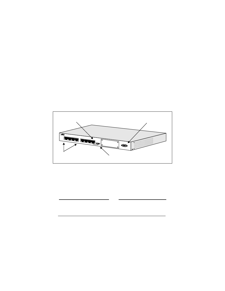
3. Insert the female end of the power cord into the Power Receptacle on the
back of the unit.
4. Insert the male end of the power cord into an electrical output of the
appropriate power.
5. Check the front panel of the hub to make sure the green power (PWR) LED
is illuminated.
6. Plug all 100BASE-TX cables into the 100BASE-TX network ports (RJ-45
connectors) on the back of the unit.
Figure 6: Standalone AT-MR908TX Back Panel
7. Ensure that the MDI /MDI-X slide switch is set to MDI-X as shown in
Figure 6. This enables the use of Port 1 for a normal network connection.
8. Plug the opposite end of each 100BASE-TX cable into a network node or
workstation.
Note
The Collision Domain Diameter (total allowable distance end-to-end)
for a Class I repeater cannot exceed 200 meters. That is, the hub-to-
device connection should never be more than 100 meters in length.
You are now ready to operate your AT-MR908TX hub in a standalone, Class I,
network configuration.
Port 1
Power receptacle
Network ports
MDI MDI-X switch (set to MDI-X)