Allied Telesis AT-MCR1 User Manual
Page 38
Chapter 2: Installation
38
A tray cable is required to connect the power source if the
chassis is powered by centralized DC power. The tray cable
must be an UL listed Type TC tray cable and rated at 600 V
and 90 degree C, with three conductors, minimum 14 AWG.
E24
1.
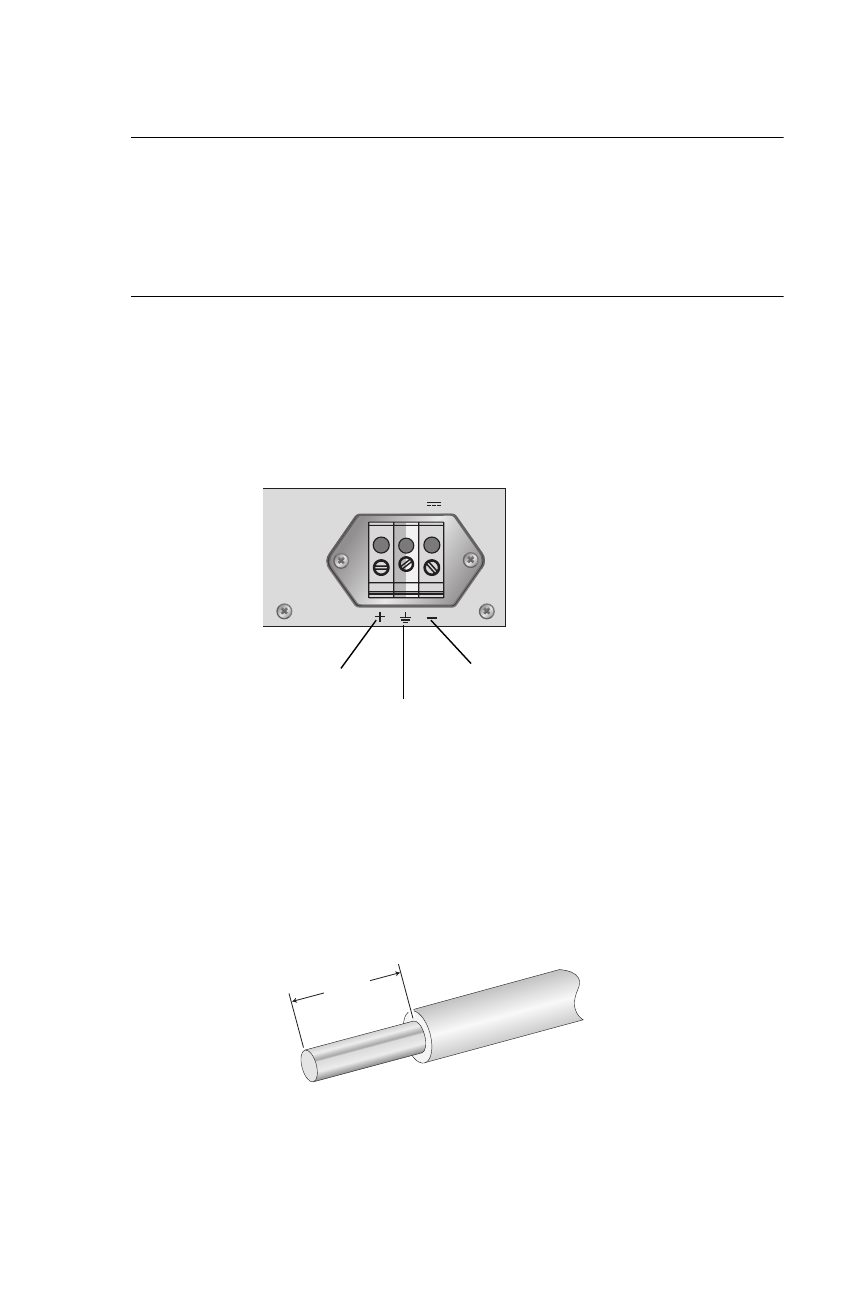
On the back panel of the chassis is a DC terminal block,
starting from the left side of the terminal block, identify the
positive, frame ground, and negative terminals, using the
symbols above the terminal block, as shown in Figure 18.
Figure 18. DC Terminal Block
2.
With a 14-gauge wire-stripping tool, strip the three wires in
the tray cable coming from the DC input power source to
8mm
± 1mm (0.31 in., ± 0.039 in.), as shown in Figure 19.
Figure 19. Stripped Wire
40-60VDC
1058
Positive
Ground
Negative
8mm ±1mm
(0.31in. ±0.039in.)
- AT-GS908M (54 pages)
- AT-x230-10GP (80 pages)
- AT-GS950/48PS (64 pages)
- AT-GS950/10PS (386 pages)
- AT-GS950/16PS (386 pages)
- AT-GS950/48PS (386 pages)
- AT-9000 Series (258 pages)
- AT-9000 Series (1480 pages)
- IE200 Series (70 pages)
- AT-GS950/48 (410 pages)
- AT-GS950/8 (52 pages)
- AT-GS950/48 (378 pages)
- AT-GS950/48 (60 pages)
- SwitchBlade x8106 (322 pages)
- SwitchBlade x8112 (322 pages)
- SwitchBlade x8106 (240 pages)
- SwitchBlade x8112 (240 pages)
- AT-TQ Series (172 pages)
- AlliedWare Plus Operating System Version 5.4.4C (x310-26FT,x310-26FP,x310-50FT,x310-50FP) (2220 pages)
- FS970M Series (106 pages)
- 8100L Series (116 pages)
- 8100S Series (140 pages)
- x310 Series (116 pages)
- x310 Series (120 pages)
- AT-GS950/24 (366 pages)
- AT-GS950/16 (44 pages)
- AT-GS950/24 (404 pages)
- AT-GS950/16 (404 pages)
- AT-GS950/16 (364 pages)
- AT-GS950/8 (404 pages)
- AT-GS950/8 (364 pages)
- AT-GS950/8 (52 pages)
- AT-8100 Series (330 pages)
- AT-8100 Series (1962 pages)
- AT-FS970M Series (330 pages)
- AT-FS970M Series (1938 pages)
- SwitchBlade x3106 (288 pages)
- SwitchBlade x3112 (294 pages)
- SwitchBlade x3106 (260 pages)
- SwitchBlade x3112 (222 pages)
- AT-S95 CLI (AT-8000GS Series) (397 pages)
- AT-S94 CLI (AT-8000S Series) (402 pages)
- AT-IMC1000T/SFP (23 pages)
- AT-IMC1000TP/SFP (24 pages)
- AT-SBx3106WMB (44 pages)