Operating mode leds, Poe pwr leds, Operating mode leds poe pwr leds – Allied Telesis AT-PC232/POE User Manual
Page 28: Table 6. operating mode leds table 7. poe pwr leds
Chapter 1: Overview
28
Operating Mode
LEDs
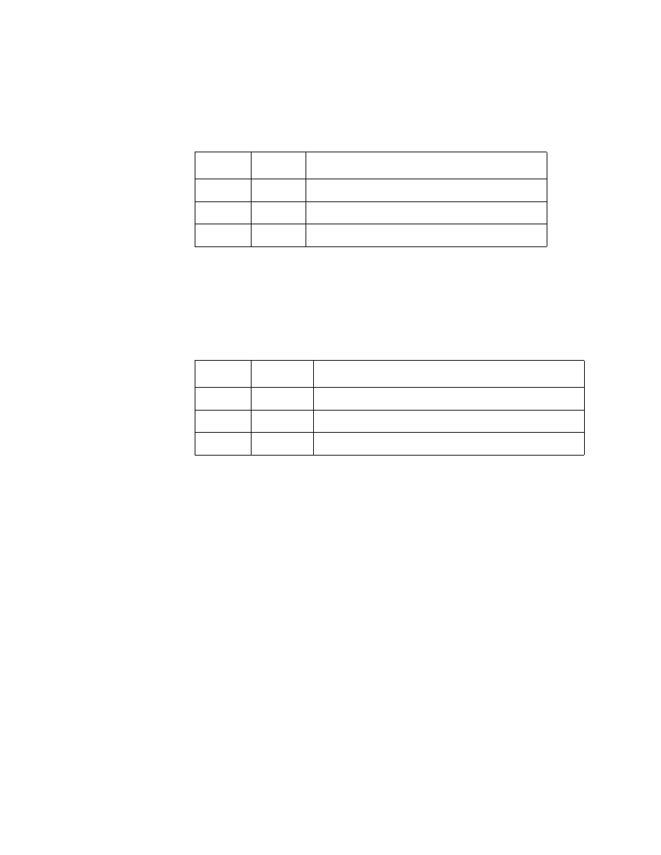
The three LEDs listed under MODE on the front panel display the
operating mode of the media converter. The LEDs are defined in Table 6
on page 28. Beside these LEDs is a button for setting the operating mode.
PoE PWR LEDs
If the end-node that is connected to the twisted pair port on the media
converter is a Powered Device (PD), you can use the three PoE PWR
LED’s to determine its class ID, as defined in the IEEE802.3af PoE
specification. The LEDs are described in Table 7 on page 28.
Table 7. PoE PWR LEDs
Table 6. Operating Mode LEDs
LED
Color
Description
ML
Green
MissingLink mode is enabled.
SML
Green
Smart MissingLink mode is enabled.
LT
Green
Link Test mode is enabled.
LED
Color
Description
4W
Green
Indicates that the PD device is Class 1..
7W
Green
Indicates that the PD device is Class 2..
15W
Green
Indicates that the PD device is Class 0 or 3..
- AT-GS908M (54 pages)
- AT-x230-10GP (80 pages)
- AT-GS950/48PS (64 pages)
- AT-GS950/10PS (386 pages)
- AT-GS950/16PS (386 pages)
- AT-GS950/48PS (386 pages)
- AT-9000 Series (258 pages)
- AT-9000 Series (1480 pages)
- IE200 Series (70 pages)
- AT-GS950/48 (378 pages)
- AT-GS950/48 (60 pages)
- AT-GS950/48 (410 pages)
- AT-GS950/8 (52 pages)
- SwitchBlade x8106 (322 pages)
- SwitchBlade x8112 (322 pages)
- SwitchBlade x8106 (240 pages)
- SwitchBlade x8112 (240 pages)
- AT-TQ Series (172 pages)
- AlliedWare Plus Operating System Version 5.4.4C (x310-26FT,x310-26FP,x310-50FT,x310-50FP) (2220 pages)
- FS970M Series (106 pages)
- 8100S Series (140 pages)
- 8100L Series (116 pages)
- x310 Series (116 pages)
- x310 Series (120 pages)
- AT-GS950/16 (44 pages)
- AT-GS950/24 (404 pages)
- AT-GS950/24 (366 pages)
- AT-GS950/16 (404 pages)
- AT-GS950/16 (364 pages)
- AT-GS950/8 (404 pages)
- AT-GS950/8 (364 pages)
- AT-GS950/8 (52 pages)
- AT-8100 Series (330 pages)
- AT-8100 Series (1962 pages)
- AT-FS970M Series (330 pages)
- AT-FS970M Series (1938 pages)
- SwitchBlade x3106 (288 pages)
- SwitchBlade x3112 (294 pages)
- SwitchBlade x3106 (260 pages)
- SwitchBlade x3112 (222 pages)
- AT-S95 CLI (AT-8000GS Series) (397 pages)
- AT-S94 CLI (AT-8000S Series) (402 pages)
- AT-IMC1000T/SFP (23 pages)
- AT-IMC1000TP/SFP (24 pages)
- AT-SBx3106WMB (44 pages)