Network topologies, Figure 3: topology 1 – Allied Telesis AT-PC2002/POE User Manual
Page 33
AT-PC2002/POE Media Converter Installation Guide
33
Network Topologies
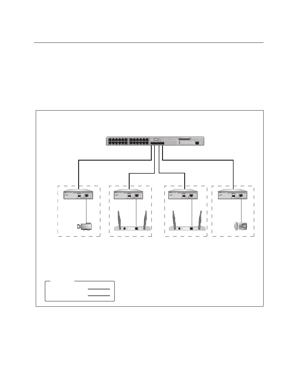
This section illustrates several topologies that incorporate the media
converter. The network in the first example consists of a central office with
the AT-9424Ts Gigabit Ethernet Switch and four remote sites that have
powered devices: a security camera, two AT-WA7400 Wireless Access
Points, and a VoIP telephone. Deployed at the remote sites are
AT-PC2002/POE Media Converters. They are powering the powered
devices over the twisted pair cables and are providing network
connectivity to the AT-9424Ts Gigabit Ethernet Switch at the central office.
Figure 3. Topology 1
Remote Site 1:
Camera
Remote Site 2:
AT-WA7400
Wireless Access
Point
Remote Site 3:
AT-WA7400
Wireless Access
Point
Remote Site 4:
VoIP Phone
Central Office:
AT-9424Ts Gigabit Ethernet Switch
with SFP Modules
Twisted pair cable
Fiber optic cable
Legend
AT-PC2002/POE
Gigabit PoE Bridging Converter
AT-PC2002/POE
Gigabit PoE Bridging Converter
5V,2.8A
RESET TO DEFAULT
LAN
AT-PC2002/POE
Gigabit PoE Bridging Converter
5V,2.8A
RESET TO DEFAULT
LAN
AT-PC2002/POE
Gigabit PoE Bridging Converter
1441