Marking the wall locations for the screw holes – Allied Telesis AT-SBx3106WMB User Manual
Page 26
Installation Instructions
26
Marking the Wall Locations for the Screw Holes
To mark the screw holes for the brackets on the wall, perform the following
procedure:
1. Position one of the wall brackets as the top bracket in the reserved
wall area for the chassis. (Either bracket can be the top bracket
because they are identical.)
Please review the following guidelines as you position the bracket on
the wall:
The bracket must be level with the floor.
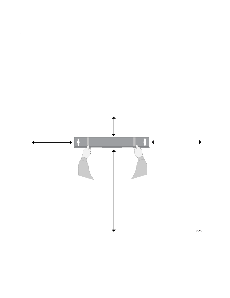
The minimum dimensions of the reserved area around the bracket
are given in Figure 8. There must not be any objects or other
devices within the area.
Figure 8. Minimum Area Dimensions When Positioning the Bracket on the
Wall
The reserved area in Figure 8 is for the chassis if it will have AC
power supplies. If the chassis will have DC power supplies, you
may reduce the reserved area for the back panel (left side) from
14.5 cm
(5 11/16 in.)
50.8 cm
(20 in.)
66.0 cm
(26 in.)
30.5 cm
(12 in.)
- AT-GS908M (54 pages)
- AT-x230-10GP (80 pages)
- AT-GS950/48PS (64 pages)
- AT-GS950/10PS (386 pages)
- AT-GS950/16PS (386 pages)
- AT-GS950/48PS (386 pages)
- AT-9000 Series (258 pages)
- AT-9000 Series (1480 pages)
- IE200 Series (70 pages)
- AT-GS950/48 (378 pages)
- AT-GS950/48 (60 pages)
- AT-GS950/48 (410 pages)
- AT-GS950/8 (52 pages)
- SwitchBlade x8106 (322 pages)
- SwitchBlade x8112 (322 pages)
- SwitchBlade x8106 (240 pages)
- SwitchBlade x8112 (240 pages)
- AT-TQ Series (172 pages)
- AlliedWare Plus Operating System Version 5.4.4C (x310-26FT,x310-26FP,x310-50FT,x310-50FP) (2220 pages)
- FS970M Series (106 pages)
- 8100L Series (116 pages)
- 8100S Series (140 pages)
- x310 Series (116 pages)
- x310 Series (120 pages)
- AT-GS950/24 (404 pages)
- AT-GS950/24 (366 pages)
- AT-GS950/16 (44 pages)
- AT-GS950/16 (404 pages)
- AT-GS950/16 (364 pages)
- AT-GS950/8 (364 pages)
- AT-GS950/8 (52 pages)
- AT-GS950/8 (404 pages)
- AT-8100 Series (330 pages)
- AT-8100 Series (1962 pages)
- AT-FS970M Series (330 pages)
- AT-FS970M Series (1938 pages)
- SwitchBlade x3106 (288 pages)
- SwitchBlade x3112 (294 pages)
- SwitchBlade x3106 (260 pages)
- SwitchBlade x3112 (222 pages)
- AT-S95 CLI (AT-8000GS Series) (397 pages)
- AT-S94 CLI (AT-8000S Series) (402 pages)
- AT-IMC1000T/SFP (23 pages)
- AT-IMC1000TP/SFP (24 pages)