Marking the screw hole locations – Allied Telesis AT-GS950/10PS User Manual
Page 49
AT-GS950/10PS, AT-GS950/16PS, and AT-GS950/48PS Switches Installation Guide
49
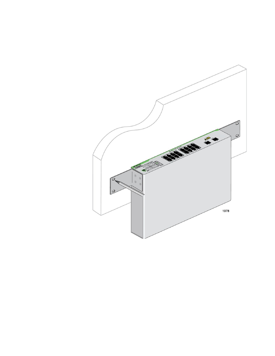
4. Have another person hold the switch at the wall location where the
switch is to be installed, while you use a pencil or pen to mark the wall
with the locations of the four holes in the brackets. The switch should
be oriented such that its front faceplate is facing up and is level to the
floor. See Figure 24.
Figure 24. Marking the Screw Hole Locations
5. Install the four plastic anchors included with the switch into the wall, at
the locations marked in the previous step. The anchors require 0.635
mm (0.25 in.) holes.
This manual is related to the following products: