Poe leds, Sfp slot led functional descriptions – Allied Telesis AT-GS950/10PS User Manual
Page 30
Chapter 1: Overview
30
PoE LEDs
All three PoE switches have two types of PoE LEDs indicating the PoE
status for each port and maximum power limit of the switch’s PoE power
supply.
Each switch model has individual PoE LEDs indicating the PoE status of
each individual port. Each chassis also has one PoE MAX LED which is
used to determine if you have exceeded the maximum power that the
chassis is capable of supplying to the powered devices (PDs).
AT-GS950/10PS and AT-GS950/16PS PoE Status LEDs
The AT-GS950/10PS switch can supply PoE power to PDs on ports 1 - 8.
See Figure 14 on page 31 for the locations of the PoE LEDs.
The AT-GS950/16PS switch can supply PoE power to PDs on ports 1 - 16.
See Figure 15 on page 31 for the location of the PoE LEDs.
The AT-GS950/48PS switch can supply PoE power to PDs on ports1 - 24.
See Figure 16 on page 31 for the location of the PoE status LEDs.
Note
See “Power over Ethernet (PoE)” on page 22 for more information
about this PoE feature.
Note
All of the port LEDs are off when the switch is operating in the low
power mode. To toggle on the LEDs, use the eco-Friendly button.
See “eco-Friendly Button” on page 33 for more information.
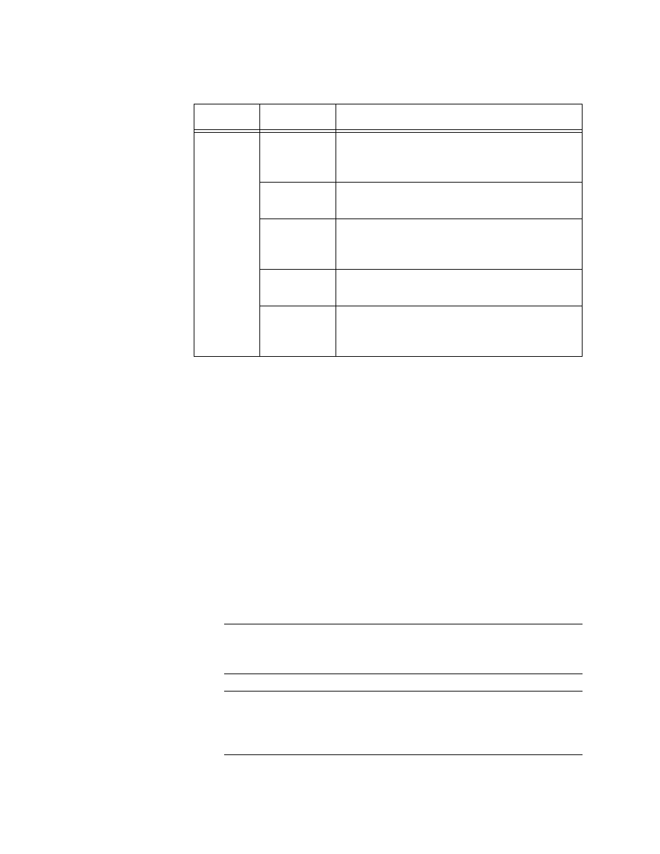
Table 7. SFP Slot LED Functional Descriptions
LED
State
Description
SFP
Off
The port on the SFP transceiver has not
established a link with an end node or the
transceiver slot is empty.
Blinking
Green
The SFP transceiver is transmitting or
receiving network packets at 1000 Mbps.
Steady
Green
The SFP transceiver has established a link
with a network device at 1000 Mbps, but is
not transmitting or receiving network packets.
Blinking
Amber
The SFP transceiver is transmitting or
receiving network packets at 100 Mbps.
Steady
Amber
The SFP transceiver has established a link
with a network device at 100 Mbps, but is not
transmitting or receiving network packets.