Smart charging regulator and power supply, Specifi cations – Campbell Scientific Solar1000 Station User Manual
Page 58
CHARGE - CHARGE Terminals (AC or DC Source)
AC:
18 to 24 V RMS with
1.2
A
RMS
maximum
DC:
16 to 40 Vdc with
1.1
A
DC
maximum
SOLAR - Terminals
1
(Solar Panel or Other DC Source)
Input
Voltage
Range:
15 to 40 Vdc
Maximum Charging Current:
3.6 Adc typical;
2.8 Adc to 4.3 Adc depending
on
individual
charger
Operational
Temperature
2
:
-40° to +60°C
Quiescent
Current
No Charge Source Present:
300 μA maximum
No Battery Connected:
2 mA maximum
Dimensions
PS200:
4.2 x 7.5 x 3 in.
(
10.6 x 19 x 7.6 cm)
CH200:
3.9 x 3 x 1.5 in.
(10 x 7.5 x 3.7 cm)
Battery Charging
3
CYCLE
Charging:
Vbatt(T) = 14.70 V –(24 mV) x (T – 25°C)
FLOAT Charging:
Vbatt(T) = 13.65 V – (18 mV) x (T – 25°C)
Accuracy:
±1% accuracy on charging
voltage
over
–40°
to
+60°C
Power Out (+12 terminals)
Voltage:
Unregulated 12 V from battery
4 A Self-Resettable Thermal Fuse Hold Current Limits
<20°C:
> 4 A
20°C:
4.0 A
50°C:
3.1 A
60°C:
2.7 A
Measurements
Average
Battery
Voltage:
±(1% of reading +15 mV)
over
–40°
to
+60°C
range
Average Battery/Load Current
Regulator
Input
Voltage
4
:
±(2% of reading +2 mA)
over
–40°
to
+60°C
range
Solar
5
:
±(1% of reading - 0.25 V) /
-(1%
of
reading
+1
V)
over
–40°
to
+60°C
range
Continuous
6
:
±(1% of reading - 0.5 V) /
-(1%
of
reading
+2
V)
over
–40°
to
+60°C
range
Charger
Temperature:
± 2°C
1
Battery voltages below 8.7 V may result in <3.0 A current limit because of fold-back current limit.
2
VRLA battery manufacturers state that “heat kills batteries” and recommend operating batteries ≤50°C.
3
Two-step temperature compensated constant- voltage charging for valve-regulated lead-acid batteries. Cycle and fl oat charging voltage
parameters are programmable with the default values listed.
4
Impulse type changes in current may have an average current error of ±(10% of reading + 2 mA).
5.
1.0 V negative off set is worst-case due to reversal protection diode on input. Typical diode drop is 0.35 V.
6.
2.0 V negative off set is worst-case due to two series diodes in AC full-bridge. Typical diode drops are 0.35 V each for 0.7 V total.
Specifi cations
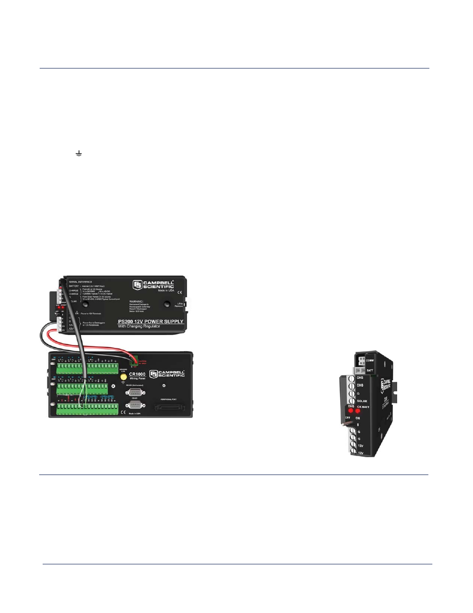
At right is a top view
of a CH200 showing its
LEDs and terminals.
CH200 and PS200
Smart Charging Regulator and Power Supply
A CR1000 is connected to the PS200 ‘s SDI-12 terminal allowing
the CR1000 to receive the PS200’s charging, load, battery volt-
age, and current information.