2 cmp6 and cmp11 wiring – Campbell Scientific Solar1000 Station User Manual
Page 52
CMP6-L, CMP11-L, and CMP21-L Pyranometers
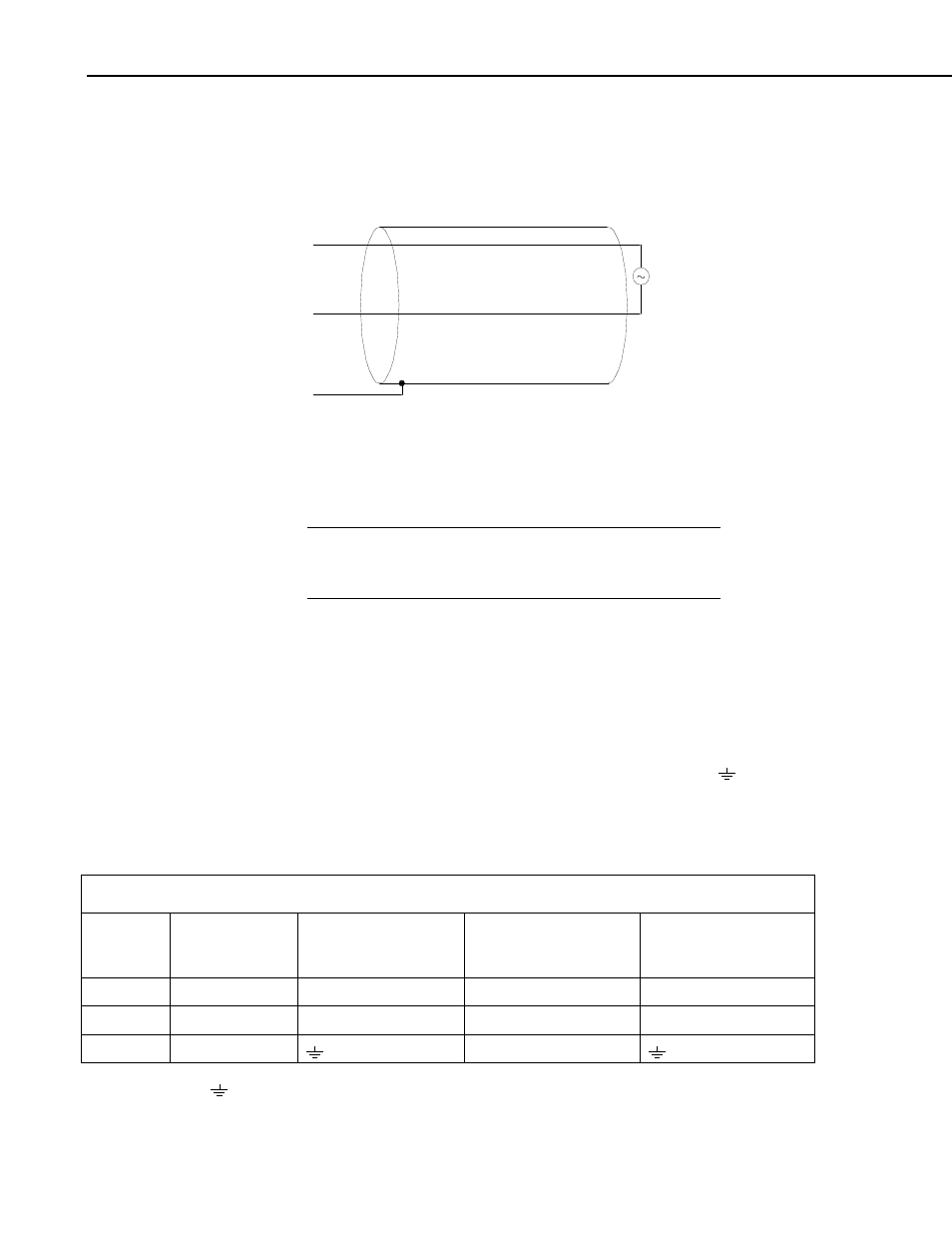
7.6.2.1 CMP6, CMP11, and CMP21 Thermopile Schematic
A schematic diagram of a CMP6, CMP11, or CMP21 thermopile is shown in
Figure
7-11.
Red
Blue
Black
Shield
Black (-)
White (+)
FIGURE 7-11. CMP6, CMP11, and CMP21 thermopile detector
schematic
7.6.2.2 CMP6 and CMP11 Wiring
A CMP6 or CMP11 purchased from Campbell Scientific has
different wiring than a pyranometer purchased directly from
Kipp & Zonen.
NOTE
The pyranometer is measured using either differential analog channels or
single-ended analog channels.
A differential voltage measurement is recommended because it has better noise
rejection than a single-ended measurement.
Connections to Campbell Scientific dataloggers for a differential measurement
are given in Table
7-2. A user-supplied jumper wire should be connected
between the low side of the differential input and ground (AG or
) to keep
the signal in common mode range.
Connections to Campbell Scientific dataloggers for a single-ended
measurement are given in Table
7-3.
TABLE 7-2. CMP6 and CMP11 Differential Connections to Campbell Scientific Dataloggers
Color
Description
CR9000(X), CR5000,
CR3000, CR1000,
CR800
CR510, CR500,
CR10(X)
21X, CR7, CR23X
White
Signal (+)
DIFF Analog High
DIFF Analog High
DIFF Analog High
Black
Signal (-)
*DIFF Analog Low
*DIFF Analog Low
*DIFF Analog Low
Shield Shield
G
* Jumper to AG or
with user supplied 26 AWG or larger wire.
48