Cr1000 specifi cations, Program execution rate, Analog inputs – Campbell Scientific Solar1000 Station User Manual
Page 56: Analog outputs, Resistance measurements, Period average, Pulse counters, Digital i/o ports (c1-c8), Switched 12 v, Ce compliance
PROGRAM EXECUTION RATE
10 ms to one day @ 10 ms increments
ANALOG INPUTS
(SE1-SE16 or DIFF1-DIFF8)
8 differential (DF) or 16 single-ended (SE) individually
configured. Channel expansion provided by AM16/32B
and AM25T multiplexers.
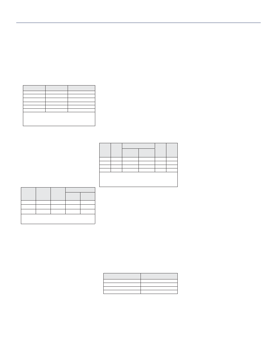
RANGES and RESOLUTION: Basic resolution
(Basic Res) is the A/D resolution of a single
conversion. Resolution of DF measurements
with input reversal is half the Basic Res.
Range (mV)
1
DF Res (µV)
2
Basic Res (µV)
±5000
667
1333
±2500
333
667
±250
33.3
66.7
±25
3.33
6.7
±7.5
1.0
2.0
±2.5
0.33
0.67
1
Range overhead of
~
9% on all ranges guarantees that
full-scale values will not cause over range.
2
Resolution of DF measurements with input reversal.
ACCURACY
3
:
±(0.06% of reading + offset), 0° to 40°C
±(0.12% of reading + offset), -25° to 50°C
±(0.18% of reading + offset), -55° to 85°C (-XT only)
3
Accuracy does not include the sensor and measurement
noise. The offsets are defined as:
Offset for DF w/input reversal = 1.5·Basic Res + 1.0 µV
Offset for DF w/o input reversal = 3·Basic Res + 2.0 µV
Offset for SE = 3·Basic Res + 3.0 µV
INPUT NOISE VOLTAGE: For DF measurements
with
input reversal on ±2.5 mV input range; digital
resolution
dominates for higher ranges.
250 µs Integration:
0.34 µV RMS
50/60 Hz Integration:
0.19 µV RMS
ANALOG MEASUREMENT SPEED:
Integra-
tion Type/
Code
Integra-
tion Time
Settling
Time
Total Time
5
SE w/
No Rev
DF w/
Input Rev
250
250 µs
450 µs
~1 ms
~12 ms
60 Hz
4
16.67 ms
3 ms
~20 ms
~40 ms
50 Hz
4
20.00 ms
3 ms
~25 ms
~50 ms
4
AC line noise filter.
5
Includes 250 µs for conversion to engineering units.
INPUT LIMITS: ±5 V
DC COMMON MODE REJECTION: >100 dB
NORMAL MODE REJECTION: 70 dB @ 60 Hz
when using 60 Hz rejection
SUSTAINED INPUT VOLTAGE W/O DAMAGE:
±16
Vdc
max.
INPUT CURRENT: ±1 nA typical, ±6 nA max.
@ 50°C; ±90 nA @ 85°C
INPUT RESISTANCE: 20 Gohms typical
ACCURACY OF BUILT-IN REFERENCE JUNCTION
THERMISTOR (for thermocouple measurements):
±0.3°C, -25° to 50°C
±0.8°C, -55° to 85°C (-XT only)
ANALOG OUTPUTS
(Vx1-Vx3)
3 switched voltage, active only during measurement,
one at a time.
RANGE AND RESOLUTION: Voltage outputs program-
mable between ±2.5 V with 0.67 mV resolution.
V
x
ACCURACY: ±(0.06% of setting + 0.8 mV), 0° to 40°C
±(0.12% of setting + 0.8 mV), -25° to 50°C
±(0.18% of setting + 0.8 mV), -55° to 85°C (-XT only)
V
x
FREQUENCY SWEEP FUNCTION: Switched outputs
provide a programmable swept frequency, 0 to 2500 mv
square waves for exciting vibrating wire transducers.
CURRENT SOURCING/SINKING: ±25 mA
RESISTANCE MEASUREMENTS
MEASUREMENT TYPES: The CR1000 provides
ratiometric measurements of 4- and 6-wire full
bridges, and 2-, 3-, and 4-wire half bridges.
Precise, dual polarity excitation using any of the
3 switched voltage excitations eliminates dc errors.
VOLTAGE RATIO ACCURACY
6
: Assuming excitation
voltage of at least 1000 mV, not including bridge
resistor
error.
±(0.04% of voltage reading + offset)/V
x
6
Accuracy does not include the sensor and measurement
noise. The offsets are defined as:
Offset for DF w/input reversal = 1.5·Basic Res + 1.0 µV
Offset for DF w/o input reversal = 3·Basic Res + 2.0 µV
Offset for SE = 3·Basic Res + 3.0 µV
Offset values are reduced by a factor of 2 when
excitation reversal is used.
PERIOD AVERAGE
Any of the16 SE analog inputs can be used for period
averaging. Accuracy is ±(0.01% of reading + resolu-
tion), where resolution is 136 ns divided by the speci-
fied number of cycles to be measured.
INPUT AMPLITUDE AND FREQUENCY:
Voltage
Gain
Input
Range
(±mV)
Signal (peak to peak)
7
Min
Pulse
Width
(µV)
Max
8
Freq
(kHz)
Min. (mV)
Max (V)
1
2500
500
10
2.5
200
10
250
10
2
10
50
33
25
5
2
62
8
100
2.5
2
2
100
5
7
With signal centered at the datalogger ground.
8
The maximum frequency = 1/(Twice Minimum Pulse Width)
for 50% of duty cycle signals.
PULSE COUNTERS
(P1-P2)
(2) inputs individually selectable for switch closure, high
frequency pulse, or low-level ac. Independent 24-bit
counters for each input.
MAXIMUM COUNTS PER SCAN: 16.7x10
6
SWITCH CLOSURE MODE:
Minimum Switch Closed Time: 5 ms
Minimum Switch Open Time: 6 ms
Max. Bounce Time: 1 ms open w/o being counted
HIGH-FREQUENCY PULSE MODE:
Maximum Input Frequency: 250 kHz
Maximum Input Voltage: ±20 V
Voltage Thresholds: Count upon transition from
below 0.9 V to above 2.2 V after input filter with
1.2 µs time constant.
LOW-LEVEL AC MODE: Internal AC coupling removes
AC offsets up to ±0.5 V.
Input Hysteresis: 12 mV @ 1 Hz
Maximum ac Input Voltage: ±20 V
Minimum ac Input Voltage:
Sine Wave (mV RMS)
Range(Hz)
20
1.0 to 20
200
0.5 to 200
2000
0.3 to 10,000
5000
0.3 to 20,000
DIGITAL I/O PORTS (C1-C8)
8 ports software selectable, as binary inputs or control out-
puts. Also provide edge timing, subroutine interrupts/wake
up, switch closure pulse counting, high frequency pulse
counting, asynchronous communications (UART), SDI-12
communications, and SDM communications.
HIGH-FREQUENCY MAX: 400 kHz
SWITCH CLOSURE FREQUENCY MAX: 150 Hz
EDGE TIMING RESOLUTION: 540 ns
OUTPUT VOLTAGES (no load): high 5.0 V ±0.1 V;
low
<0.1
OUTPUT RESISTANCE: 330 ohms
INPUT STATE: high 3.8 to 16 V; low -8.0 to 1.2 V
INPUT HYSTERESIS: 1.4 V
INPUT RESISTANCE: 100 kohms
SWITCHED 12 V
(SW-12)
One independent 12 V unregulated sources switched on
and off under program control. Thermal fuse hold current
= 900 mA @ 20°C, 650 mA @ 50°C, 360 mA @ 85°C.
CE COMPLIANCE
STANDARD(S) TO WHICH CONFORMITY IS
DECLARED: IEC61326:2002
COMMUNICATIONS
RS-232 PORTS:
9-pin: DCE port for battery-powered computer or
non-CSI modem connection.
COM1 to COM4: Four independent Tx/Rx pairs on
control ports (non-isolated); 0 to 5 VUART
Baud Rates: selectable from 300 bps to 115.2 kbps.
Default Format: 8 data bits; 1 stop bits; no parity
Optional Formats: 7 data bits; 2 stop bits; odd, even
parity
CS I/O PORT: Interface with CSI peripherals
SDI-12: Digital control ports 1, 3, 5, and 7 are
individually configured and meet SDI-12 Standard
version 1.3 for datalogger mode. Up to ten SDI-12
sensors are supported per port.
PERIPHERAL PORT: 40-pin interface for attaching
CompactFlash or Ethernet peripherals
PROTOCOLS SUPPORTED: PakBus, Modbus, DNP3,
FTP, HTTP, XML, POP3, SMTP, Telnet, NTCIP, NTP,
SDI-12,
SDM
CPU AND INTERFACE
PROCESSOR: Renesas H8S 2322 (16-bit CPU with
32-bit internal core)
MEMORY: 2 MB of Flash for operating system; 4 MB
of battery-backed SRAM for CPU usage, program
storage and data storage.
CLOCK ACCURACY: ±3 min. per year. Correction
via GPS optional.
SYSTEM POWER REQUIREMENTS
VOLTAGE: 9.6 to 16 Vdc (reverse polarity protected)
EXTERNAL BATTERIES: 12 Vdc nominal
TYPICAL CURRENT DRAIN:
Sleep Mode: 0.7 mA (0.9 mA max.)
1 Hz Sample Rate (1 fast SE meas.): 1 mA
100 Hz Sample Rate (1 fast SE meas.): 16.2 mA
100 Hz Sample Rate (1 fast SE meas. w/RS-232
communication): 27.6 mA
Optional Keyboard Display On (no backlight): add
7 mA to current drain
Optional Keyboard Display On (backlight on): add
100 mA to current drain
PHYSICAL
DIMENSIONS: 9.4" x 4" x 2.4" (23.9 x 10.2 x 6.1 cm);
additional clearance required for serial cable and
sensor leads.
WEIGHT: 2.1 lbs (1 kg)
WARRANTY
3-years against defects in materials and workmanship.
CR1000 Specifi cations
Electrical specifi cations are valid over a -25° to +50°C range unless otherwise specifi ed; non-condensing environment required. To maintain electrical
specifi cations, Campbell Scientifi c recommends recalibrating dataloggers every two years. We recommend that the system confi guration and critical
specifi cations are confi rmed with Campbell Scientifi c before purchase.