4 connect, 5 serial sensors, 4 tcp serial client – Campbell Scientific NL200/NL201 Network Link Interface User Manual
Page 28: Connect, Serial sensors, Tcp serial client, 3. serial server loggernet setup
NL200/201 Network Link Interface
•
You can verify your settings are correct by selecting the datalogger in the
Network Map, selecting the Clock tab, and pressing
Check Clocks. If
your settings are correct, you should see the current clock of your server
and datalogger.
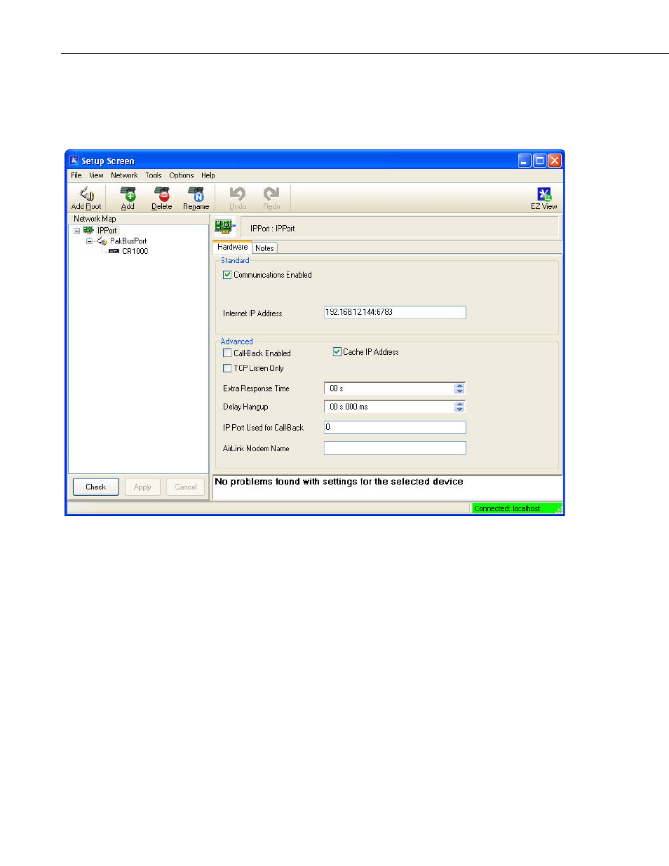
FIGURE 7-3. Serial server LoggerNet setup
7.3.4 Connect
You are now ready to connect to your datalogger using the LoggerNet Connect
screen.
7.3.5 Serial Sensors
The NL200/201 configured as an RS-232 serial server as described above can
be used to communicate with a serial sensor. However, LoggerNet is not
capable of communicating with the serial sensor. You must have some other
method of communicating with the sensor.
7.4 TCP Serial Client
When the RS-232 port is configured as
TCP Serial Client, the NL200/201 will
initiate and maintain a TCP socket connection to the IP address and port
number specified by the
Serial Client Address and Serial Client Port
settings. Data received on the RS-232 port will be forwarded to this TCP
18