Campbell Scientific EC150 CO2 and H2O Open-Path Gas Analyzer and EC100 Electronics with Optional CSAT3A 3D Sonic Anemometer User Manual
Page 62
Appendix B. Filter Bandwidth and Time Delay
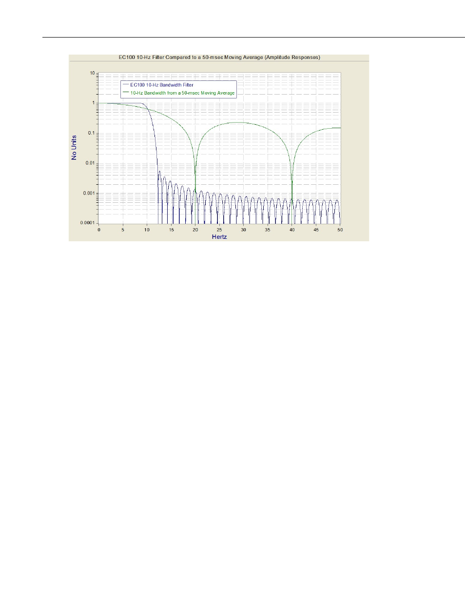
FIGURE B-2. Frequency response comparison of EC100 10-Hz
bandwidth and a 50-msec moving average
The ideal eddy-covariance filter is one that is wide enough to preserve the low-
frequency signal variations that transport flux, yet narrow enough to attenuate
high-frequency noise. In addition, to minimize aliasing (defined as the
misinterpretation of high-frequency variation as lower-frequency variation), the
measurement bandwidth must be less than half of the sample rate or the
datalogger scan rate.
Two factors complicate choosing the ideal eddy-covariance bandwidth. First,
the flux signal bandwidth varies from one installation to another, and the flux
signal bandwidth varies with mean wind speed at a given installation. Second,
the fast sample rate required to anti-alias a desired signal bandwidth may result
in large, unwieldy data sets.
Fortunately, the covariance calculation itself relaxes the need for the ideal
bandwidth. The time-averaged (typically thirty minutes) covariance
calculations inherently reduce noise, and second, aliasing does not degrade the
accuracy of covariance calculations. The factory default for the EC100
bandwidth (20 Hz) is rather wide to preserve the signal variations that transport
flux. The default bandwidth is suitable for most flux applications. Additional
bandwidths are available for users desiring to match the EC100 filter
bandwidth to their data acquisition sample rate to avoid aliasing. In this case,
the selected bandwidth should be one-half of the sample rate. However, users
should be careful to avoid attenuation of flux-carrying signals.
The EC100 electronics synchronously sample the EC150 analyzer and the
CSAT3A sonic head. However, users wishing to synchronize their EC100 data
with other measurements (for example, a fine-wire thermocouple) in the data
acquisition system must account for the time delay of the EC100 filter.
TABLE B-1 shows the delay for each of the filter bandwidths. The EC100
B-2