Rs-530 interface, V.35 interface, Appendix e: connector pinouts 120 – ADTRAN 1200051L6 User Manual
Page 134: Figure e-2, Table e-b, Figure e-3, V .35
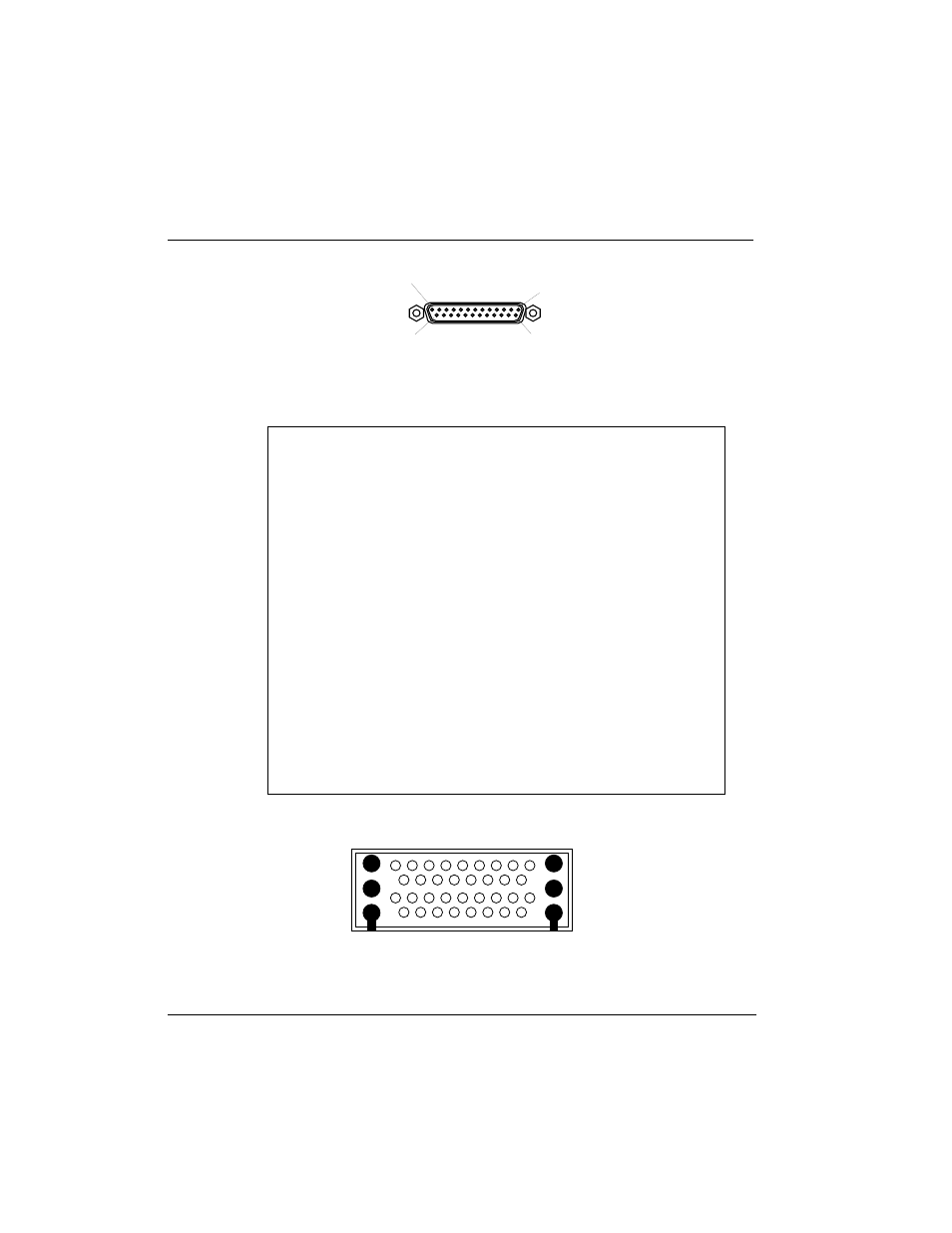
Appendix E: Connector Pinouts
120
ISU 2x64 Dual Port ISDN Service Unit User Manual
61200051L1-1D
Figure E-2
RS-530 Interface
Table E-B
RS-530 Interface
Pin
Name
I/O
Description
1 ........................... Shield ................... I/O ........ Shield for cable
2 ........................... TD-A ..................... I ............. Transmitted Data
3 ........................... RD-A ..................... O........... Received Data
4 ........................... RTS-A .................... I ............. Request To Send
5 ........................... CTS-A ................... O........... Clear To Send
6 ........................... DSR-A ................... O........... Data Set Ready
7 ........................... SG ....................... I/O ........ Signal Ground
8 ........................... CD-A .................... O........... Carrier Detect
9 ........................... RC-B ..................... O........... Receive Clock (return)
10 ......................... CD-B..................... O........... Carrier Detect (return)
11 ......................... ETC-B.................... I ............. External Transmit Clock (return)
12 ......................... TC-B ..................... O........... Transmit Clock (return)
13 ......................... CTS-B.................... O........... Clear To Send (return)
14 ......................... TD-B...................... I ............. Transmit Data (return)
15 ......................... TC-A ..................... O........... Transmit Clock
16 ......................... RD-B ..................... O........... Receive Data (return)
17 ......................... RC-A ..................... O........... Receive Clock
18 ......................... NC ...................... N/A....... No Connection
19 ......................... RTS-B .................... I ............. Request To Send (return)
20 ......................... DTR-A.................... I ............. Data Terminal Ready
21 ......................... NC ...................... N/A....... No Connection
22 ......................... DSR-B.................... O........... Data Set Ready (return)
23 ......................... DTR-B .................... I ............. Data Terminal Ready (return)
24 ......................... ETC-A ................... I ............. External Transmit Clock
25 ......................... NC ...................... N/A....... No Connection
I = Input ..............O = Output ....... N/A = Not Applicable
Figure E-3
V.35 Interface
PIN 13
PIN 1
PIN 25
PIN 14
FEMALE
V .35
A
B
C
D
E
F
J
L
R
V
Z
DD
JJ
NN
N
T
X
BB
FF
LL
K
P
U
Y
CC
HH
MM
H
S
W
AA
EE
KK
M