Electrical system – U.S. Products TREADMASTER User Manual
Page 33
27 - TreadMaster Information and Operating Instructions
EN
ELECTRICAL SYSTEM
Refer to Figure 18 - Figure 20 for the 120 V wiring diagram and electrical schematic, and
refer to Figure 21 and Figure 22 for the 230 V wiring diagram and electrical schematic.
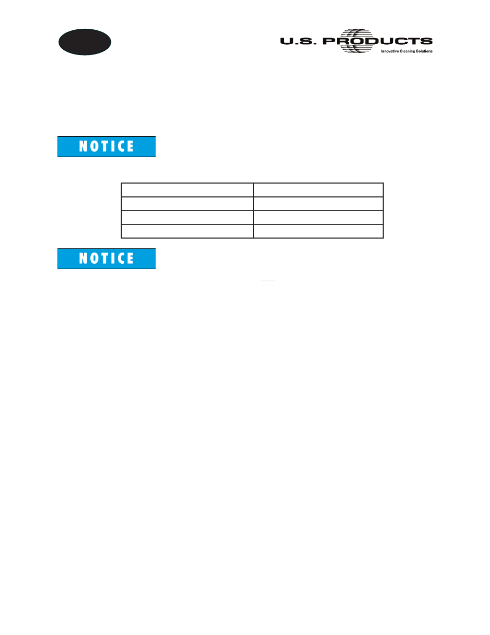
Wires are colored in accordance with the following code:
120 V Configuration
230 V Configuration
Green/Yellow - Ground
Green/Yellow - Ground
Blue - Neutral
Blue - Live
Brown - Live
Brown - Live
The power cord for the following models is not supplied by the manufacturer; it
must be supplied by the operator:
• 100-100-221
• 100-100-222
• 100-100-223