U.S. Products TREADMASTER User Manual
Page 20
TreadMaster Information and Operating Instructions - 14
EN
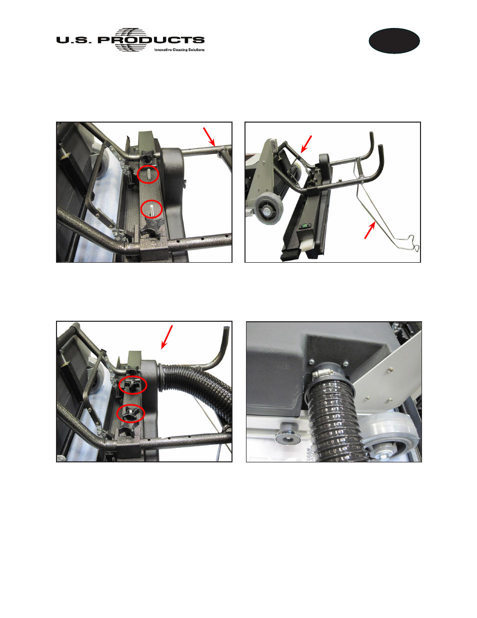
3. Position the housing assembly’s lift arm onto the head assembly, aligning the
mounting holes on the lift arm with the fasteners on the head assembly (see
Figure 4).
4. Secure the head assembly to the lift arm by re-installing the two fluted knobs (see
Figure 5).
5. Attach the vacuum hose between the housing and the cleaning nozzle. The hose
connector with the shorter end should be connected to the cleaning nozzle assembly
(see Figure 5). The hose connector with the longer end is connected to the housing
(see Figure 6) and should be secured by tightening the clamp.
Figure 4. Position Pad Holder Lift Arm on Head Assembly
Lift Arm
Lift Arm
Latching Bail
Handle
Figure 5. Secure Head Assembly
with Fluted Knobs;
Attach Hose to Nozzle
Figure 6. Attach Other End of Hose to
Housing Assembly