3 connecting up the vi-m3 & vi-m4, 4 setting date/time, Connecting up the vi-m3 & vi-m4 – Videoswitch Vi-M series User Manual
Page 10: Setting date/time, Digital recorder
Digital Recorder
1.3
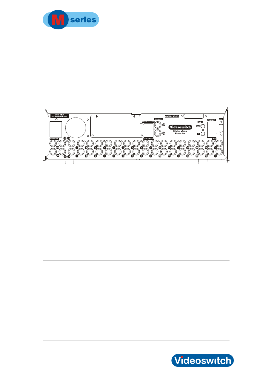
Connecting up the Vi-M3 & Vi-M4
For a standard digital recording system you will need
• The
Vi-M3
recorder
• Some cameras with lenses
• A video monitor (with BNC composite video input) or a VGA monitor
• BNC
cables
• Connect the monitor output (MAIN) of the Vi-M3 to a Video Monitor using a BNC
cable. Alternatively or additionally, connect a VGA monitor to the VGA output
• Make sure that the monitor termination is switched on (i.e. to 75 Ohms)
• Up to 3 other spot monitors may be connected to outputs M2, M3 and M4 (or 2 spot
monitor on 12-camera models)
• Connect a camera to Camera Input 1 on the Vi-M3using a BNC cable
• Connect further cameras to Inputs 2,3,4 etc
• Make sure that the voltage select switch (if present) is set to suit the mains supply.
The setting required in UK and Europe is normally 230Vac.
• Connect the mains power using the mains cable provided
1.4 Setting
Date/Time
For proper operation of the M-series DVR Digital Recorder it is essential that the date
and time are set correctly.
If the system clock has an invalid date or time when the M-series DVR is powered up or at
any time during operation, the displayed date and time in live mode will replaced by dashes.
If the clock needs setting, refer to section 1.1.7 page 21.
Note that the time is automatically adjusted forwards or backwards by an hour at the
appropriate dates to take account of British Summertime (daylight saving) so no user action
is required.
4