Evc/epc controller, With sae j1939 interface – High Country Tek epc, Electronic Pump Controller - A Multi-Function SAE J1939 Compatible Module User Manual
Page 22
023-00354-Rev1.6
evc/epc User Manual
22
Copyright © High Country Tek, Inc.
– 2013
evc/epc Controller
With SAE J1939 Interface
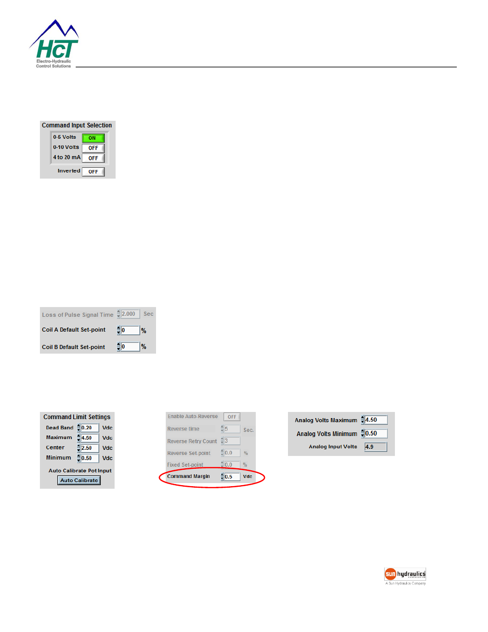
Command Input Selection
0-5VDC
0-10VDC
4-20mA
Inverted
– reverses the response of the command input to output current.
i.e., Minimum command input will give 100% output current and the
Maximum command input gives 0% output current.
For industrial applications that use ±5VDC or ±10VDC, please use a HCT Command Signal Conditioner with the
evc/epc controller.
CSC-0505
– accepts ±5VDC and converts to 0-5V.
CSC-1005
– accepts ±10VDC and converts to 0-5V.
Loss of Pulse Signal Time
– (1mS to 65Sec) Sets the time delay
before an error of loss of
any “Pulse signal” causes to be declared.
Coil A or B default set-point
– (0-100%) Output A or B will ramp to
this value when the input limits are exceeded or J1939 message times
out, or reference voltage drops to below 4VDC, or the supply voltage
drops to below 9VDC, or the pulse signal is lost.
Command Limit Settings