Dashboard, Evc/epc controller, With sae j1939 interface – High Country Tek epc, Electronic Pump Controller - A Multi-Function SAE J1939 Compatible Module User Manual
Page 16
023-00354-Rev1.6
evc/epc User Manual
16
Copyright © High Country Tek, Inc.
– 2013
evc/epc Controller
With SAE J1939 Interface
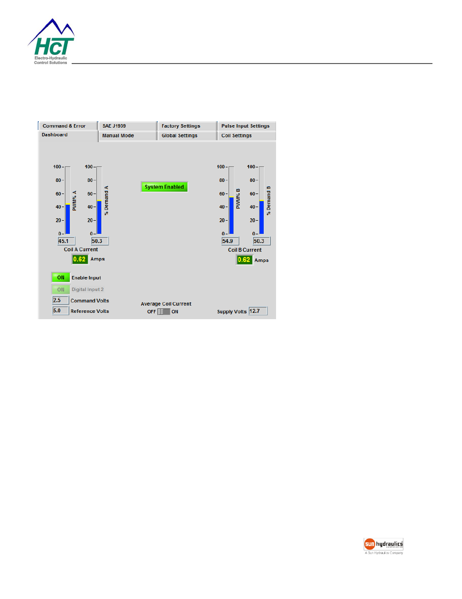
Dashboard
PWM% A/B
– displays the PWM duty
cycle output for coil A and B. The
PWM% B will be “Grayed Out” when
Coil B is disabled.
% Demand A/B
–
displays the percent
of demand for the output with respect
to the Maximum and Minimum Current
settings. The % Demand B will be
“Grayed Out” when Coil B is disabled.
Coil Current A/B
– displays the output
current. The Coil B Current will be
“Grayed Out” when Coil B is disabled.
Enabled/Disabled
– displays the current state of the enable input.
Command Volts/mAmps
– Displays the voltage or current at the Command input.
Reference Volts
– Displays the voltage at the User Reference output.
Supply Volts
– Displays the voltage at the main Power Supply Input.
Average Coil Current
– Applies averaging function to the displayed coil current. It does not affect coil current.
B