Command & error settings, Evc/epc controller, With sae j1939 interface – High Country Tek epc, Electronic Pump Controller - A Multi-Function SAE J1939 Compatible Module User Manual
Page 21
023-00354-Rev1.6
evc/epc User Manual
21
Copyright © High Country Tek, Inc.
– 2013
evc/epc Controller
With SAE J1939 Interface
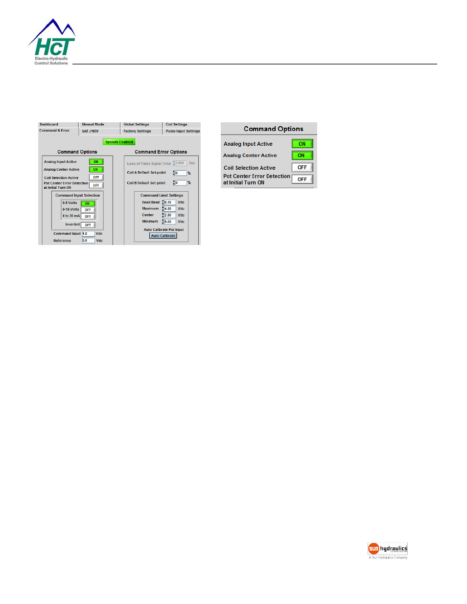
Command & Error Settings
Analog Input Active (On/Off)
– Enables/Disables
the command analog input.
Analog Center Active (On/Off)
When enabled, the
“Pot Center Voltage” becomes the zero demand point.
Coil A is driven from the center voltage to the max voltage and coil B is driven from the center voltage to the min
voltage
This setting is used in Dual Coil Valve Control only. The
“Coil Selection Active” switch is automatically turned
OFF when the Center Active
is “ON”.
Coil Selection Active (On/Off)
When the input is High, (+5V to Supply Volts) coil B is active and when Low (0V to 2.5V) coil A is active.
This feature allows the full command resolution on coil A and B.
As an example, it is used in the applications where a reciprocating action is triggered by a single high-low input.
Pot Center Error Detection at Initial Turn On
When ON, the module verifies the analog input is in the center deadband range before enabling the output(s)
after the initial power up.
Once the command is centered, the outputs will be enabled.
This safety feature ensures that the system will NOT immediately go to the previous settings after cycling the
power.