Status leds defi ned, Relay output (fmor01) – AMETEK 2120 PLC Interface Module User Manual
Page 9
Installation and Programming Manual
Chapter 2: Hardware Overview
5
2.3: Status LEDs Defi ned
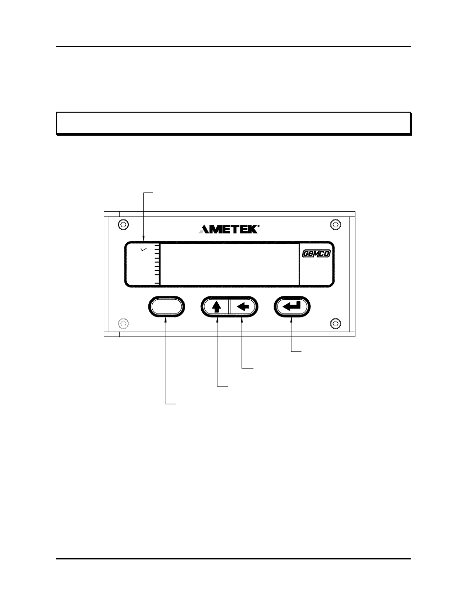
The Interface Module has 10 status LEDs and four programming keys. The LEDs provide information on
the monitor’s state during machine operation, and the programming keys are used to program functions
and perform basic operations.
Figure 2-2 Status LEDs and Programming Keys
PROGRAM
The program LED turns on when the Interface Module is in program mode and
turns off when it is not. Functions cannot be programmed when this LED is off.
FAULT
OK
The fault check OK LED turns on when the power supply’s fault check relay is
energized, indicating the system is OK. This LED will turn off when a fault is
detected, indicating that the fault check relay is deenergized.
MVT FLT
The movement fault LED turns on when a movement fault is detected. (For more
information, see Move Detection Time-out in Section 4.3: Setup Functions.)
Relay Output (FMOR01)
This optional module contains two overtravel limit relays. These relays can be programmed to either
energize or deenergize upon reaching the programmed overtravel position. These relays will also actuate
upon detection of the system and operating errors listed in chart A-5 in Appendix A.
Status LEDs
Shift Key
Scroll Key
Function Key
Enter Key
AUX 3
AUX 2
AUX 1
PROGRAM
FLT OK
MVT FLT
POSITION
UPR LIM
LWR LIM
RPM
2120
SERIES
F
( )