Wiring, Controller module (fmmp01), Relay output module (fmor01) – AMETEK 2120 PLC Interface Module User Manual
Page 14
10
Installation and Programming Manual
Chapter 3: Mounting and Wiring
This section contains pinout diagrams for each module. System wiring diagrams follow.
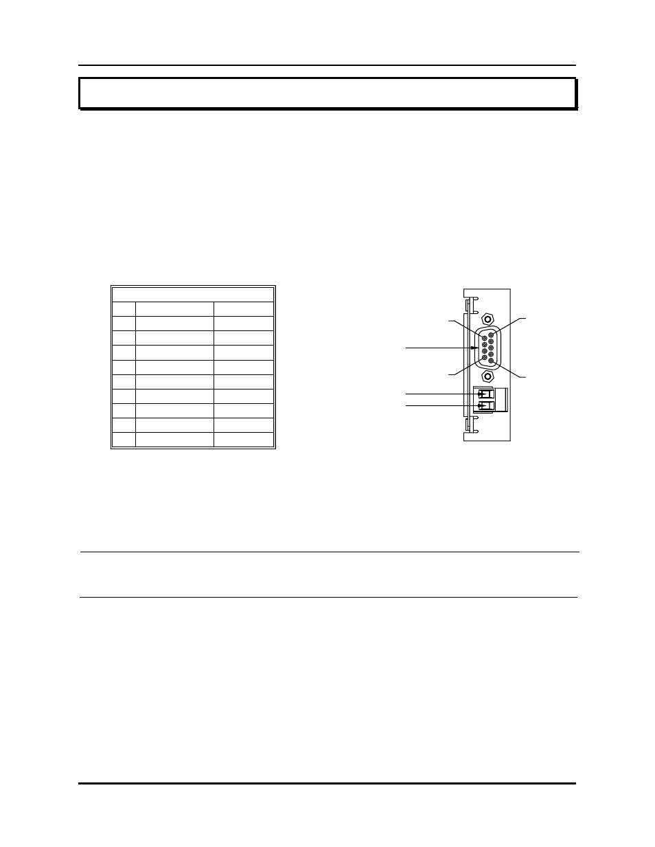
Controller Module (FMMP01)
The controller has two connectors: a D9 connector (J1) for RS-232 and RS-485 serial
communications, and a program lockout connector (J2) intended for a keyswitch. (See Figure
3-2). Making connections to both connectors is optional. However, the program lockout
connector must be jumpered to allow the unit to enter program mode. J2’s input rating is +5
VDC maximum dry contact or open collector (drain) only. Actuation voltage must be less than
+1.0 VDC at 0.2 mA. The terminal wire size is No. 22-12 AWG.
Figure 3-2 Controller Pinout Diagram
Drawing E8002099
NOTE: The controller’s program lockout connector (J2) must be jumpered to allow the unit
to enter program mode.
Relay Output Module (FMOR01)
The relay output module contains two overtravel limit relays. Each relay contains a N.O. contact
pair and a separate N.C. contact pair. (See Figure 3-3). The relay contacts are rated at 8 amps
250 VAC, 30 VDC, 1/4 HP 125, 250 VAC. The terminal wire size is 22-12 AWG.
COMMUNICATIONS CONNECTOR
PIN SIGNAL NAME DIRECTION
OUTPUT
INPUT
INPUT
OUTPUT
4
NO CONNECTION
9
8
7
6
5
CTS RS-232
TX2- RS-485
GND SIGNAL
RTS RS-232
TX2+ RS-485
I / O
I / O
3
2
1
GND CHASSIS
RXD RS-232
TXD RS-232
{
(J2)
INPUT -
INPUT +
PIN 6
CONNECTOR D9 FEMALE
COMMUNICATIONS (J1)
PIN 9
PIN 1
FMMP01
2
1
PIN 5
C.P.U.
3.2: Wiring