AMETEK 2120 PLC Interface Module User Manual
Page 51
Installation and Programming Manual
Appendix A: Error Messages
47
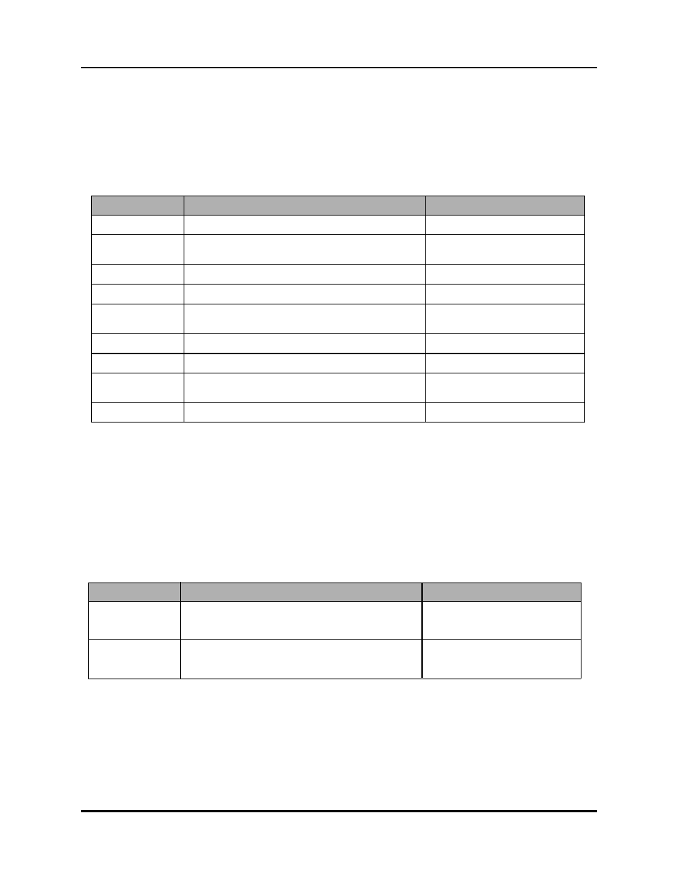
The following charts contain descriptions and solutions for the three types of errors that can
appear on the monitor’s LED display. To clear errors, perform the solutions found in charts A-1,
A-2, and A-3, followed by pressing either the scroll, shift, or enter.
Chart A-1 System Errors
Chart A-2 Operating Errors
Error Displayed
Error Description
Solution
SEr101
SEr102
SEr103
A confi guration error has occured
Contact the factory
The monitor’s function parameter memory has
been corrupted
The battery for the monitor’s memory is low
SEr104
A software fault has occurred
SEr105
An error has occurred with the monitor’s
internal memory locations.
SEr106
A fi rmware CRC error has occurred
SEr320
This is a resolver-specifi c error
SEr330
The input device is not connected to the monitor’s
input module
SEr331
This is an LDT-specifi c error.
Contact the factory
Contact the factory
Contact the factory
Clear error and contact
factory
Contact the factory
Contact the factory
See chart A-6
See chart A-7
Error Displayed
Error Description
Solution
OEr101
OEr330 or
OEr320
The machine did not move within the time pro-
grammed in the Move Detection Time-Out function
Review machine operation and/or
increase the value of the Move
Detection Time-Out function
The Interface Module moved beyond the value pro-
grammed in the Negative Over Travel Limit function
Review machine operation and/or
increase the value of the negative
Over Travel Limit function