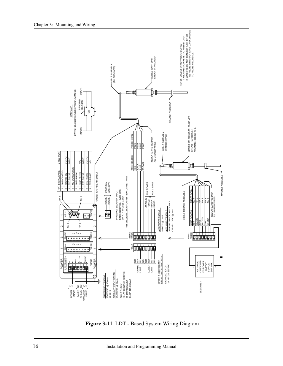
Figure 3-11 ldt - based system wiring diagram – AMETEK 2120 PLC Interface Module User Manual
Page 20
See also other documents in the category AMETEK Sensors:
- 925 Linear Cable Reel Sensor (1 page)
- 925 Linear Cable Reel Sensor (2 pages)
- 925 Linear Cable Reel Sensor (8 pages)
- 955C Brik (71 pages)
- 950 MD Mill Duty Housing LDT (10 pages)
- 952 BlueOx LDT (36 pages)
- 953 VMAX LDT (18 pages)
- 955 eBrik (2 pages)
- 955 eBrik (6 pages)
- 955A Brik LDT (4 pages)
- 955D LDT (12 pages)
- 955DQ Brik LDT (24 pages)
- 955LC Brik LDT (1 page)
- 955S Smart Brik LDT (8 pages)
- 956 Blok Housing Option (2 pages)
- 957 SSI Brik (20 pages)
- 1970 Drive Check Control (4 pages)
- 1980 Rotating Cam Limit Switch (20 pages)
- 1980R Rotating Cam Limit Switch w/Resolver (20 pages)
- 1986 DN DeviceNet Resolver (20 pages)
- 1986I 4 (2 pages)
- 7014 Unifloat Level Float Sensors (4 pages)
- 7230 HT Digital Probe (2 pages)
- 7230 HT Digital Probe (25 pages)
- 7330 Pro-Stik II (2 pages)
- 7330 Pro-Stik II (12 pages)
- 7100 Leak Detect Stik (4 pages)
- 7100 Leak Detect Stik (22 pages)
- 7250 Digital Stick (2 pages)
- 7250 Digital Stick (11 pages)
- 1500 Induction Style Relay (6 pages)
- 5200 Solid State Relay (4 pages)
- 5400 Plug In Style Solid State Relay (2 pages)
- Over Temperature Protection (2 pages)
- Electro-Thrust Shoe Brakes (2 pages)
- 1746 LDT Interface Card (24 pages)
- 1746 LDT Interface Card (28 pages)
- 1746 LDT Interface Card (2 pages)
- 1990 DN DeviceNet Resolver Interface Module (20 pages)
- 1995A Micro-Set PLS (38 pages)
- 1995B Micro-Set PLS with Brake Monitor (40 pages)
- 1995L Micro-Set PLS (33 pages)
- 2110 Shut Height Monitor (59 pages)
- 1025 Foot & Palm Switches (24 pages)