ARI Armaturen ARI-PACO 0,85kN EN User Manual
Page 26
Page 26
0040506000 1811
Operating and installation instructions
Electric thrust actuator ARI-PACO 0,85 kN
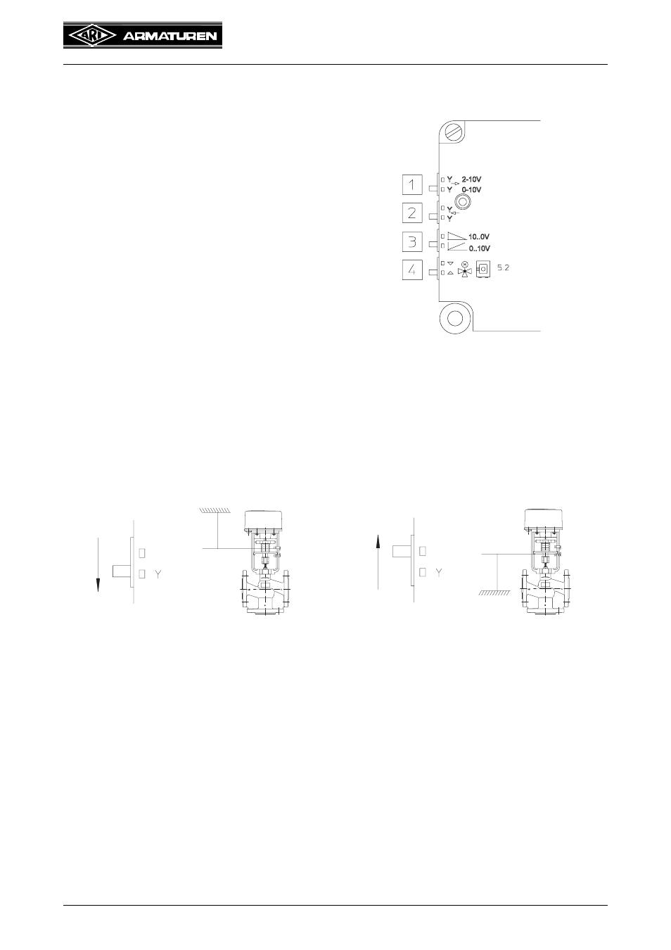
6.2.5 Adaptation of the valve functions, ARI-PACO 0,85 Y
The valve function is set with 4 switches beneath the actuating drive housing.
Switch 1
Adjustment of the actuating signals Y from
the regulator 0...10 V DC or 2...10 V
Fig. 34
Switch 2
Actuating singal output:
Adjustment only necessary for connected
actuating signal output.
Fig. 35: Upper valve end position,
Position signal output = 10 V
Fig. 36: Lower valve end position,
Position signal output = 10 V
See also other documents in the category ARI Armaturen Equipment:
- STOBU PN 16 EN (13 pages)
- STOBU PN63-160 EN (18 pages)
- Metallic sealing EN (11 pages)
- FABA-Plus EN (15 pages)
- EURO-WEDI EN (10 pages)
- FA160 EN (17 pages)
- ASTRA DN15-80 EN (12 pages)
- ASTRA Plus DN15-80 EN (13 pages)
- CHECKO-D DN 125-350 EN (8 pages)
- CHECKO-V PN6-160 EN (12 pages)
- Strainer PN6-160 (10 pages)
- BR012-ZESA EN (15 pages)
- SAFE900 EN (18 pages)
- ARI REYCO R971 EN (18 pages)
- PREDU 700 EN (17 pages)
- STEVI 405 DN 15-250 EN (18 pages)
- STEVI 405 DN 300-500 EN (16 pages)
- STEVI BBD 415 DN 25-50 EN (18 pages)
- STEVI 440 EN (21 pages)
- STEVI 450 EN (22 pages)
- STEVI 423 EN (16 pages)
- STEVI 423 DN300 EN (14 pages)
- STEVI 470 EN (1 page)
- STEVI 470 EN (16 pages)
- STEVI 422 EN (16 pages)
- STEVI 425 EN (16 pages)
- STEVI H 485 EN (14 pages)
- WA 306H EN (14 pages)
- CONA B PN16 EN (15 pages)
- CONA Universal ANSI 300 EN (17 pages)
- CONA all-in-one PN40 EN (18 pages)
- CONA M PN16 EN (13 pages)
- CONA M PN16 EN (12 pages)
- CONA S PN16 EN (9 pages)
- CONA S PN40 EN (15 pages)
- CONA S PN63 EN (18 pages)
- CONA S PN25 EN (11 pages)
- CONA S PN40 EN (13 pages)
- CONA SC PN16 EN (16 pages)
- CONA TD PN40 EN (13 pages)
- CODI S PN40 EN (13 pages)
- Condensate PN40 EN (14 pages)
- Liquid PN25 EN (11 pages)
- 0040807002 EN (2 pages)
- Steam injector PN25 EN (8 pages)