4 electrical connection, 1 wiring diagram ari-paco 0,85 d, 2 wiring diagram ari-paco 0,85 y – ARI Armaturen ARI-PACO 0,85kN EN User Manual
Page 12
Page 12
0040506000 1811
Operating and installation instructions
Electric thrust actuator ARI-PACO 0,85 kN
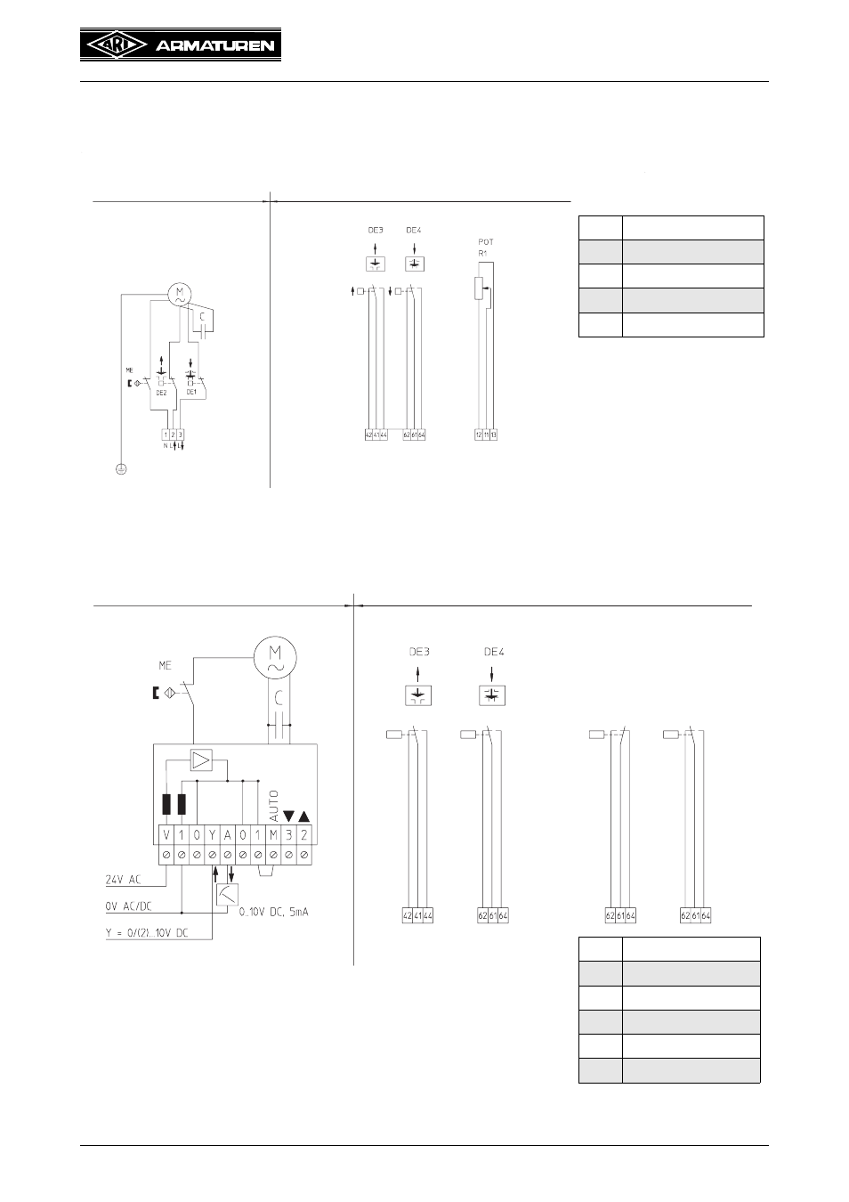
5.4 Electrical connection
5.4.1 Wiring diagram ARI-PACO 0,85 D
Fig. 6
5.4.2 Wiring diagram ARI-PACO 0,85 Y
Fig. 7
DE
Torque swittch
POT
Potentiometer
ME
Magnet switch
M
Motor
C
Capacitor
Standard
Accessories
DE
Torque swittch
POT
Potentiometer
ME
Magnet switch
M
Motor
C
Capacitor
D
Diode
Standard
Accessories
2. Function
(message switch)
no error
error
With input signals 0/2-10 V a bridge, connecting the terminals 1 and M, has
to be installed. In case of a three-step controller signal the bridge is not
required. A signal at the terminals 2 and 3 e.g. from an anti-freezing
contact has always priority over the input signal.
For automatic operation, a jumper 1 / M must be installed, the priority
switching is preserved
1. Function
- STOBU PN 16 EN (13 pages)
- STOBU PN63-160 EN (18 pages)
- Metallic sealing EN (11 pages)
- FABA-Plus EN (15 pages)
- EURO-WEDI EN (10 pages)
- FA160 EN (17 pages)
- ASTRA DN15-80 EN (12 pages)
- ASTRA Plus DN15-80 EN (13 pages)
- CHECKO-D DN 125-350 EN (8 pages)
- CHECKO-V PN6-160 EN (12 pages)
- Strainer PN6-160 (10 pages)
- BR012-ZESA EN (15 pages)
- SAFE900 EN (18 pages)
- ARI REYCO R971 EN (18 pages)
- PREDU 700 EN (17 pages)
- STEVI 405 DN 15-250 EN (18 pages)
- STEVI 405 DN 300-500 EN (16 pages)
- STEVI BBD 415 DN 25-50 EN (18 pages)
- STEVI 440 EN (21 pages)
- STEVI 450 EN (22 pages)
- STEVI 423 EN (16 pages)
- STEVI 423 DN300 EN (14 pages)
- STEVI 470 EN (1 page)
- STEVI 470 EN (16 pages)
- STEVI 422 EN (16 pages)
- STEVI 425 EN (16 pages)
- STEVI H 485 EN (14 pages)
- WA 306H EN (14 pages)
- CONA B PN16 EN (15 pages)
- CONA Universal ANSI 300 EN (17 pages)
- CONA all-in-one PN40 EN (18 pages)
- CONA M PN16 EN (13 pages)
- CONA M PN16 EN (12 pages)
- CONA S PN40 EN (15 pages)
- CONA S PN63 EN (18 pages)
- CONA S PN25 EN (11 pages)
- CONA S PN16 EN (9 pages)
- CONA S PN40 EN (13 pages)
- CONA SC PN16 EN (16 pages)
- CONA TD PN40 EN (13 pages)
- CODI S PN40 EN (13 pages)
- Condensate PN40 EN (14 pages)
- Liquid PN25 EN (11 pages)
- 0040807002 EN (2 pages)
- Steam injector PN25 EN (8 pages)