ARI Armaturen ARI-PACO 0,85kN EN User Manual
Page 17
0040506000 1811
Page 17
Operating and installation instructions
Electric thrust actuator ARI-PACO 0,85 kN
5.5.2.2 Connection and adjustment of the switching module in the ARI-PACO 0,85 D
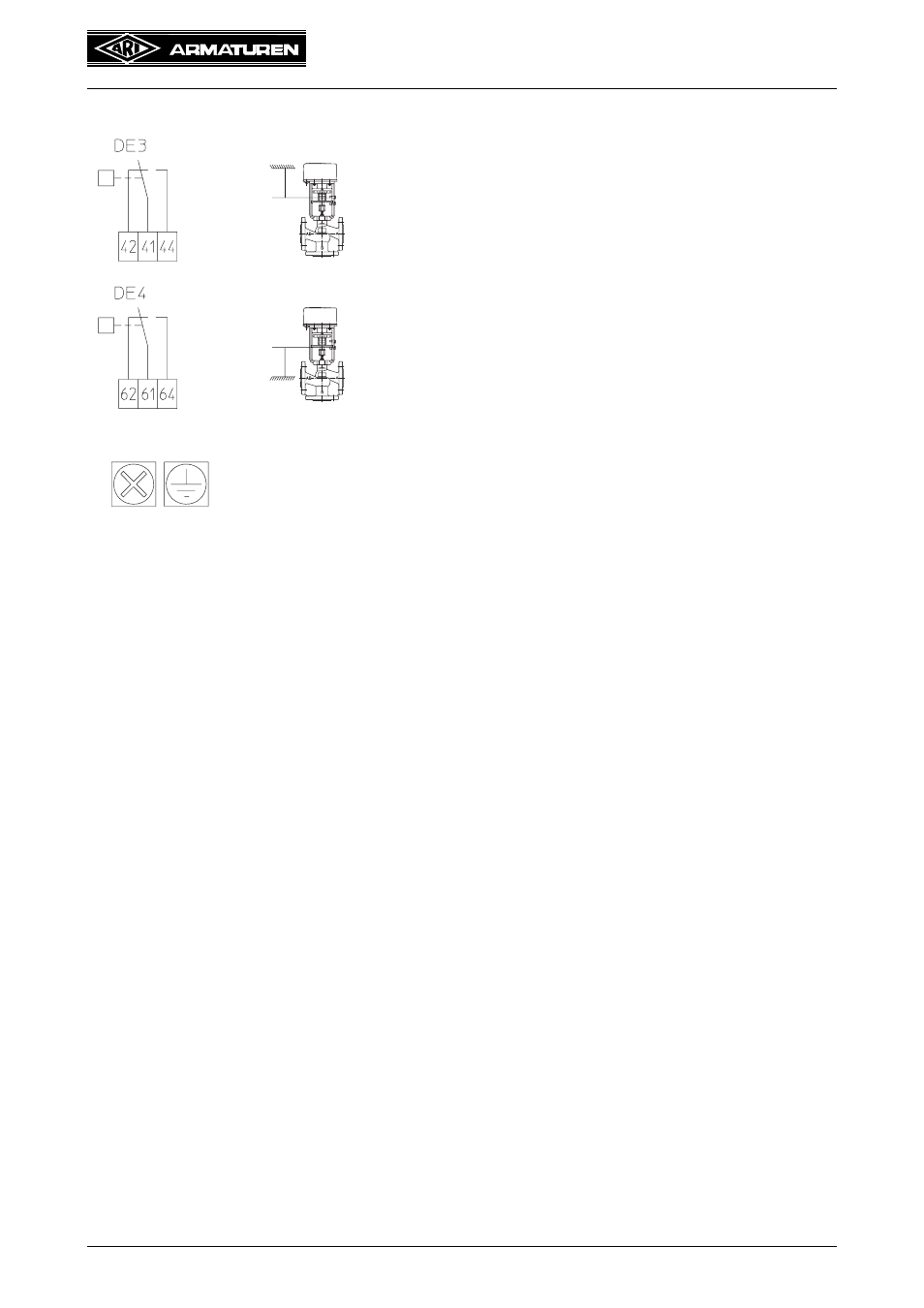
Fig. 14
Fig. 12 shows how the electrical
connection should be made.
No further adjustments are required.
After the electrical connection is
made, the housing should be
carefully seated from above and
fastened with two recessed screws
on the linear actuator (Fig. 11). Move
sliding switch on the housing to
automatic, switch on mains and test
function controls
Contact switches in
the upper end position
from
41-42 to 41-44
Contact switches in
the lower end position
from
61-62 to 61-64
max. 250VAC, 3A
See also other documents in the category ARI Armaturen Equipment:
- STOBU PN 16 EN (13 pages)
- STOBU PN63-160 EN (18 pages)
- Metallic sealing EN (11 pages)
- FABA-Plus EN (15 pages)
- EURO-WEDI EN (10 pages)
- FA160 EN (17 pages)
- ASTRA DN15-80 EN (12 pages)
- ASTRA Plus DN15-80 EN (13 pages)
- CHECKO-D DN 125-350 EN (8 pages)
- CHECKO-V PN6-160 EN (12 pages)
- Strainer PN6-160 (10 pages)
- BR012-ZESA EN (15 pages)
- SAFE900 EN (18 pages)
- ARI REYCO R971 EN (18 pages)
- PREDU 700 EN (17 pages)
- STEVI 405 DN 15-250 EN (18 pages)
- STEVI 405 DN 300-500 EN (16 pages)
- STEVI BBD 415 DN 25-50 EN (18 pages)
- STEVI 440 EN (21 pages)
- STEVI 450 EN (22 pages)
- STEVI 423 EN (16 pages)
- STEVI 423 DN300 EN (14 pages)
- STEVI 470 EN (1 page)
- STEVI 470 EN (16 pages)
- STEVI 422 EN (16 pages)
- STEVI 425 EN (16 pages)
- STEVI H 485 EN (14 pages)
- WA 306H EN (14 pages)
- CONA B PN16 EN (15 pages)
- CONA Universal ANSI 300 EN (17 pages)
- CONA all-in-one PN40 EN (18 pages)
- CONA M PN16 EN (12 pages)
- CONA M PN16 EN (13 pages)
- CONA S PN16 EN (9 pages)
- CONA S PN40 EN (15 pages)
- CONA S PN63 EN (18 pages)
- CONA S PN25 EN (11 pages)
- CONA S PN40 EN (13 pages)
- CONA SC PN16 EN (16 pages)
- CONA TD PN40 EN (13 pages)
- CODI S PN40 EN (13 pages)
- Condensate PN40 EN (14 pages)
- Liquid PN25 EN (11 pages)
- 0040807002 EN (2 pages)
- Steam injector PN25 EN (8 pages)