ARI Armaturen ARI-PACO 0,85kN EN User Manual
Page 19
0040506000 1811
Page 19
Operating and installation instructions
Electric thrust actuator ARI-PACO 0,85 kN
5.5.3.2 Connection and adjustment of the relay card in the ARI-PACO 0,85 Y
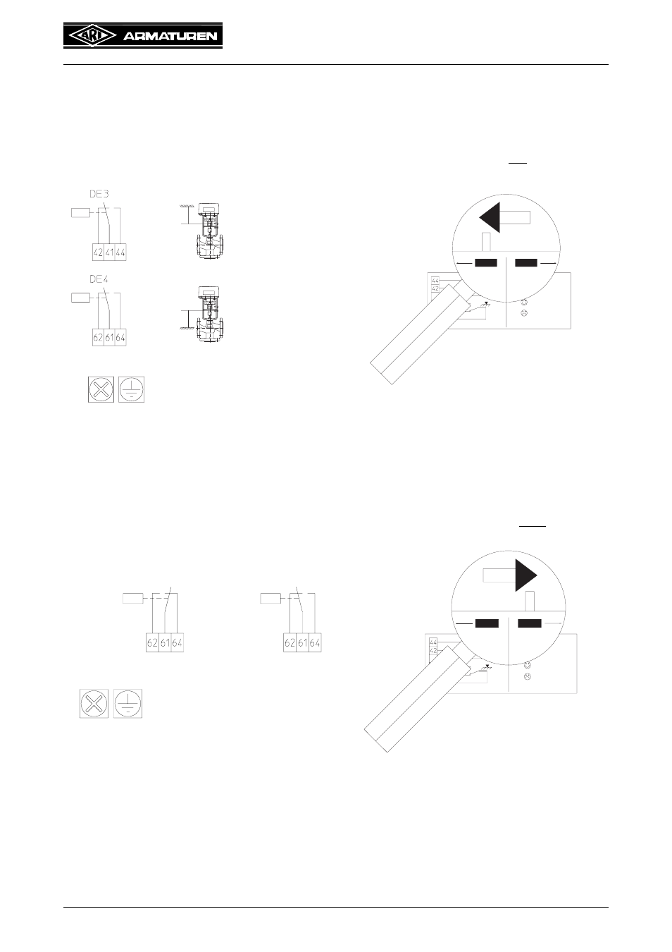
Two functions can be switched with the relay card.
1. function:
2. function:
After the electrical connections and the function adjustment are made, remount the housing
carefully from above and fasten with two recessed screws on the linear actuator. Set the
sliding switch on the housing on automatic operation, switch on mains and carry out a
function control.
Feedback of the two valve positions OPEN/
SHUT:
(The relay contacts are voltage-free)
Fig. 18
Position sliding swith to the left !!
Fig. 19
Malfunction message monitoring for valve
blockage and power loss of the 24V
voltage supply:
(The relay contacts are voltage-free)
Fig. 20
Position sliding switch to the right !
Fig. 21
max. 250VAC, 3A
Contact switches in
the upper end
position from
41-42 to 41-44
Contact switches in
the lower end
position from
41-42 to 41-44
no malfunction
malfunction
max. 250VAC, 3A
- STOBU PN 16 EN (13 pages)
- STOBU PN63-160 EN (18 pages)
- Metallic sealing EN (11 pages)
- FABA-Plus EN (15 pages)
- EURO-WEDI EN (10 pages)
- FA160 EN (17 pages)
- ASTRA DN15-80 EN (12 pages)
- ASTRA Plus DN15-80 EN (13 pages)
- CHECKO-D DN 125-350 EN (8 pages)
- CHECKO-V PN6-160 EN (12 pages)
- Strainer PN6-160 (10 pages)
- BR012-ZESA EN (15 pages)
- SAFE900 EN (18 pages)
- ARI REYCO R971 EN (18 pages)
- PREDU 700 EN (17 pages)
- STEVI 405 DN 15-250 EN (18 pages)
- STEVI 405 DN 300-500 EN (16 pages)
- STEVI BBD 415 DN 25-50 EN (18 pages)
- STEVI 440 EN (21 pages)
- STEVI 450 EN (22 pages)
- STEVI 423 EN (16 pages)
- STEVI 423 DN300 EN (14 pages)
- STEVI 470 EN (1 page)
- STEVI 470 EN (16 pages)
- STEVI 422 EN (16 pages)
- STEVI 425 EN (16 pages)
- STEVI H 485 EN (14 pages)
- WA 306H EN (14 pages)
- CONA B PN16 EN (15 pages)
- CONA Universal ANSI 300 EN (17 pages)
- CONA all-in-one PN40 EN (18 pages)
- CONA M PN16 EN (13 pages)
- CONA M PN16 EN (12 pages)
- CONA S PN16 EN (9 pages)
- CONA S PN40 EN (15 pages)
- CONA S PN63 EN (18 pages)
- CONA S PN25 EN (11 pages)
- CONA S PN40 EN (13 pages)
- CONA SC PN16 EN (16 pages)
- CONA TD PN40 EN (13 pages)
- CODI S PN40 EN (13 pages)
- Condensate PN40 EN (14 pages)
- Liquid PN25 EN (11 pages)
- 0040807002 EN (2 pages)
- Steam injector PN25 EN (8 pages)