3 assembly instructions to the mounting on valves, 1 mounting of valve ari-paco 0,85 kn – ARI Armaturen ARI-PACO 0,85kN EN User Manual
Page 11
0040506000 1811
Page 11
Operating and installation instructions
Electric thrust actuator ARI-PACO 0,85 kN
5.3 Assembly instructions to the mounting on valves
If the valve is already mounted at the plant, care must be taken that before the drive
is assembled, no pressure difference occurs in the valve body.
If necessary, close shut-off slide valve or switch off pump
.
5.3.1 Mounting of valve ARI-PACO 0,85 kN
Fig. 5
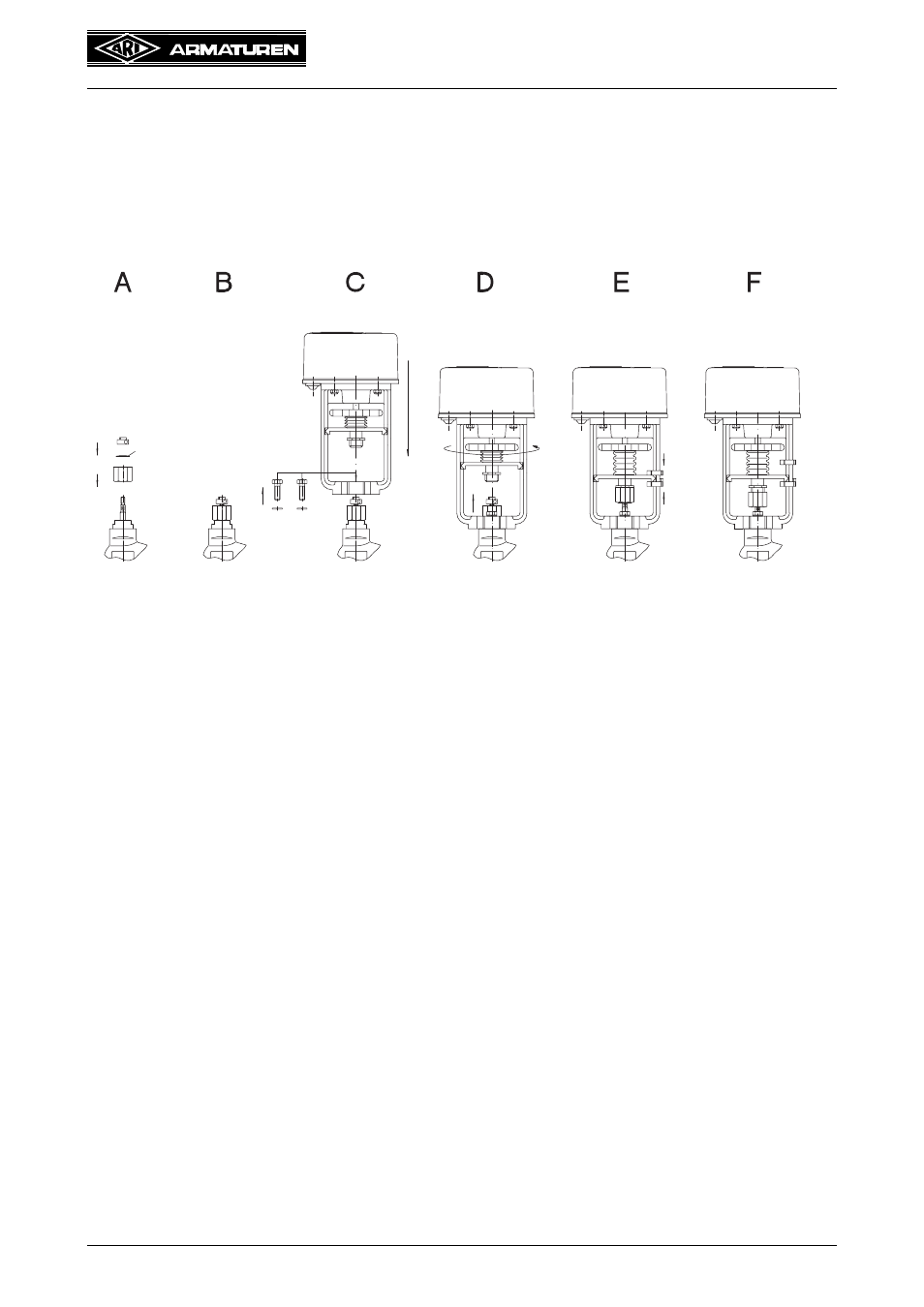
Mount the linear actuator on a valve in the following way:
- screw the coupling out of the torque protection of the linear actuators.
- bring the valve cone about in the middle of the actuating range.
Bild A:
- push the coupling over the valve stem.
Bild B:
- Zumscrew the screw socket with toothed plate appropriate to the valve on
the valve stem and secure with hexagon socket screw.
Bild C:
- set linear actuator on the valve
- fasten linear actuator with two hex screws (M8 x 22) and two spring washers
onto the armature.
Bild D:
- move the torque protection with the hand wheel until it lies on the screw
socket.
- tighten the coupling by hand and then secure with a wrench (SW24) at an
angle of max. 1 x 100° - 110° (refer also to notice on the drive hood)
Bild E:
- push upper and lower setting mark of the travel display to the torque
protection.
Bild F:
- move the actuating drive into both end positions and determine that they can
be reached with certainty. For type ARI-PACO 0,85, execute an initialization
run (refer to pt. 6.2.1 )
- the setting marks of the travel display move to the correct position when the
end positions are set.
- make electrical connections (refer to pt. 5.4 ).
washer
turn