Red Lion ZMD - MINIATURE QUAD User Manual
Model zmd – miniature length sensor, Replaces model lsm), Description
1
MODEL ZMD – MINIATURE LENGTH SENSOR
(Replaces MODEL LSM)
DESCRIPTION
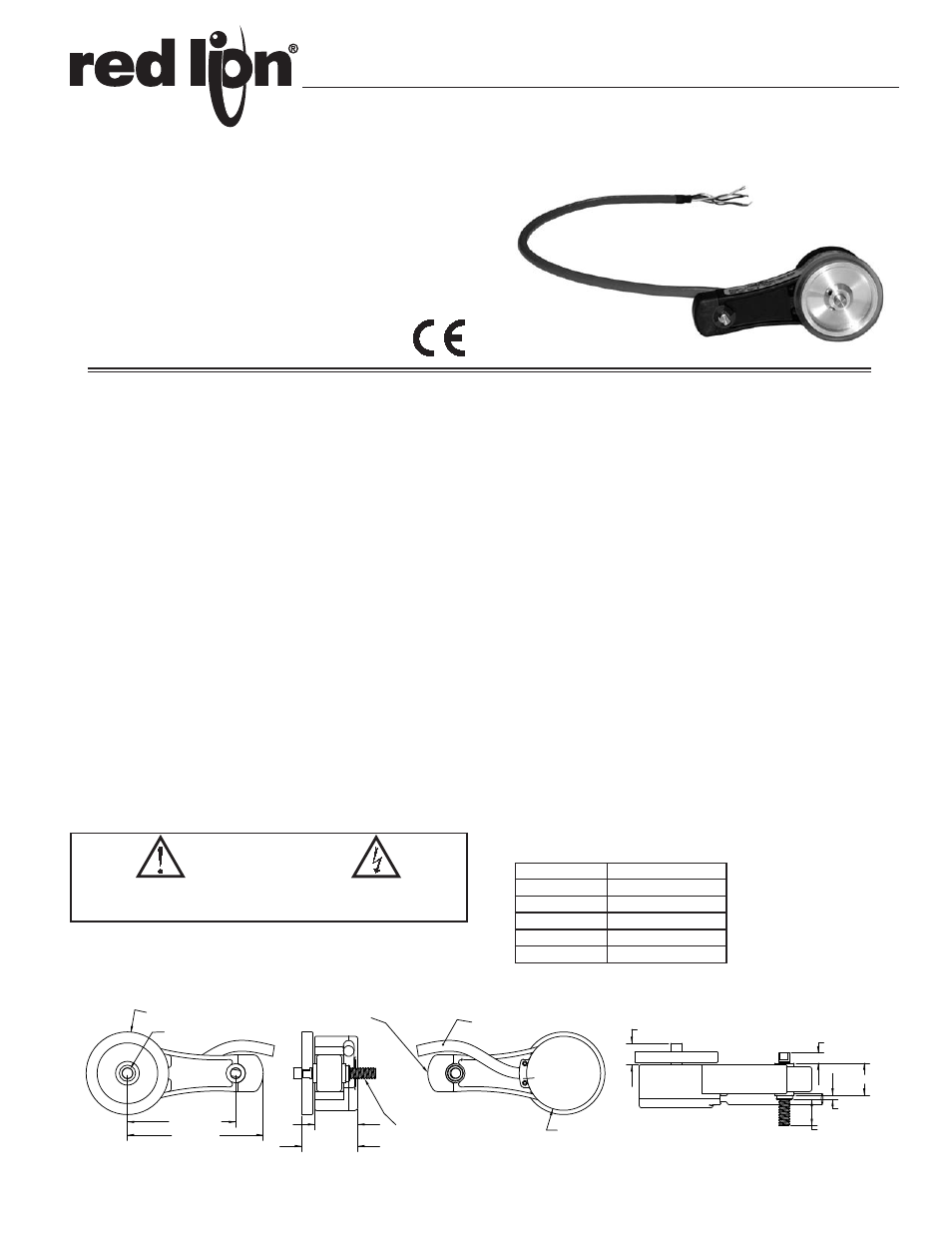
Designed for light to medium duty sensing applications, the Miniature Length
Sensor, Model ZMD, is compact in size and easy-to-use.
It features a built-in spring-loaded torsion arm that provides a simple-to-
adjust torsion load, allowing the unit to be mounted in almost any orientation,
including upside down. Using a 6" or 200 mm wheel, the ZMD can be used on
almost any surface, while operating at speeds up to 3000 feet per minute. The
housing is a durable, conductive composite material that will eliminate static
build up. Whether you need to measure speed, position, or distances, the Model
ZMD is the ideal solution. For other pulse rates and/or wiring configurations,
contact the factory for further details.
Open Collector Output Wiring
The ZMD sensors have open collector outputs. An open collector output
brings the uncommitted collector of the encoder switching device to the external
world. Because the collector element is not associated with the sensor supply
voltage, the sensor output collector may be “pulled up” to external voltages
different than the encoder supply voltage (30 VDC maximum). NPN open
collector outputs are current sinking devices. An output signal will not be
generated unless a pull-up resistor is connected from the open-collector to the
positive side of an external supply. The same supply can be used for powering
the unit and for the pull-up resistor.
SAFETY SUMMARY
All safety related regulations, local codes and instructions that appear in the
literature or on equipment must be observed to ensure personal safety and to
prevent damage to either the instrument or equipment connected to it. If
equipment is used in a manner not specified by the manufacturer, the protection
provided by the equipment may be impaired.
SPECIFICATIONS
ELECTRICAL SPECIFICATIONS
1. INPUT VOLTAGE: 4.75 to 28 VDC max for temperatures up to 85ºC; 4.75
to 24 VDC for temperatures between 85ºC to 100ºC, reverse polarity
protected.
2. INPUT CURRENT: 100 mA max (65 mA typical) with no output load
3. OUTPUTS: NPN Open Collector Transistor, V
OH
= 30 VDC max.; 20 mA
max. current. Incremental - Two square waves in quadrature with A leading
B for clockwise rotation, as viewed from the wheel side.
4. MAX FREQUENCY: 200 KHz standard
5. NOISE IMMUNITY: Tested to BS EN61000-6-2; BS EN50081-2; BS
EN61000-4-2; BS EN61000-4-3; BS EN61000-4-6, BS EN500811 (Tested
with 2 meter cable)
6. SYMMETRY: 180º (±18º) electrical
7. QUAD. PHASING: 90º (±22.5º) electrical
8. MIN. EDGE SEP: 67.5º electrical
9. ACCURACY: Within 0.017º mechanical or 1 arc-minute from true position.
(for PPR>189)
MECHANICAL SPECIFICATIONS
1. MAXIMUM MECHANICAL SPEED: 6000 RPM. Higher speeds may be
achievable, contact the factory.
2. SHAFT MATERIAL: Stainless Steel
3. SHAFT TOLERANCE: +0.0000/-0.0004" (+0.000/-0.010 mm)
4. RADIAL SHAFT LOAD: 5 lb. max. Rated load of 2 to 3 lb for bearing life
of 1.2 x 10
10
revolutions
5. AXIAL SHAFT LOAD: 5 lb. max. Rated load of 2 to 3 lb for bearing life of
1.2 x 10
10
revolutions
6. STARTING TORQUE: 0.05 oz-in
7. ELECTRICAL CONNECTION: 2 meter Cable, (foil and braid shield, 24
AWG conductors). Drain wire internally connected to case.
FUNCTION
CABLE WIRE COLOR
+VDC
Red
Com
Black
A
White
B
Green
Shield
Bare
Bulletin No. ZMD-B
Drawing No. LP0733
Released 07/12
Tel +1 (717) 767-6511
Fax +1 (717) 764-0839
www.redlion.net
6.000 CIRCUMFERENCE (ordered separately)
Metric wheel available
"L"
SIDE
Ш0.2498 (Ш5.995)
1/4-20 or M6 THREADS AVAILABLE
SHAFT CAN BE REVERSED FOR
MOUNTING FROM EITHER SIDE
"R"
SIDE
CABLE LENGTH
2 meter STANDARD
TORQUE ADJUSTMENT
UNDER RUBBER CAP
Ø
1.71 (43.4)
1.00 (25.3)
1.3 (33)
TYPICAL
0.740 (18.8)
0.100 (2.54)
"R" SIDE
0.60 (15.2)
0.50 (12.6)
0.24 (6)
"L" SIDE
3.13 (79.6)
2.500 (63.5)
CAUTION: Read complete
instructions prior to installation
and operation of the unit.
CAUTION: Risk of electric shock.
DIMENSIONS In inches (mm)
Tolerance: x.xxx" = ±0.005"
x.xx" = ±0.01"
COMPACT SIZE
QUADRATURE OUTPUT
BUILT-IN SPRING TENSIONING
VERTICAL, HORIZONTAL, OR UPSIDE-DOWN MOUNTING
REDUCES INSTALLATION TIME
VARIOUS MEASURING WHEELS AVAILABLE