Trouble shooting, Installation, Output wiring – Red Lion CTD User Manual
Page 2: Range select, Ordering information
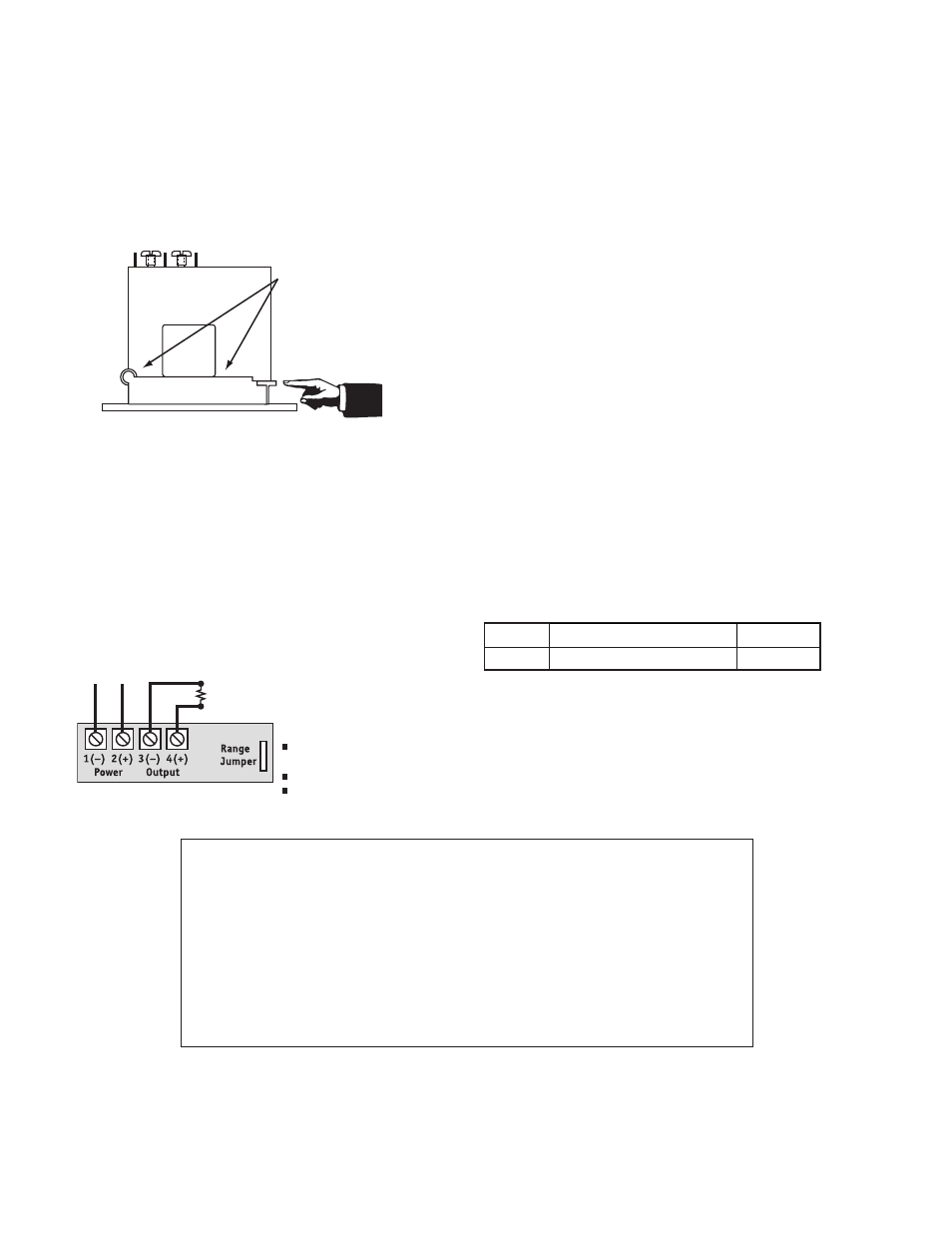
INSTALLATION
Run wire to be monitored through opening in the sensor. Be sure the
monitored current flows in the same direction as the arrow on the sensor. The
arrow is just above the hinge, with the “+” symbol on the left, the “-” symbol on
the right. The CTD transducers work in the same environment as motors,
contactors, heaters, pull-boxes, and other electrical enclosures. They can be
mounted in any position or hung directly on wires with a wire tie. Just leave at
least one inch (25.4 mm) distance between sensor and other magnetic devices.
Split-Core Versions
Press the tab in the direction as shown to open the sensor. After placing the
wire in the opening, press the hinged portion firmly downward until a definite
click is heard and the tab pops out fully.
KEEP SPLIT-CORE SENSORS CLEAN.
Silicone grease is factory applied on the mating surfaces to prevent rust and
improve performance. Be careful not to allow grit or dirt onto the grease in the
contact area. Operation can be impaired if the mating surfaces do not have good
contact. Check visually before closing.
OUTPUT WIRING
Connect control or monitoring wires to the sensor. Use up to 14 AWG copper
wire and tighten terminals to 4 inch-pounds torque.
4-20mA:
The current loop is powered by the CTD Transducer.
Maximum loop impedance is 650
Ω.
RANGE SELECT
CTD transducers feature field selectable ranges. The ranges are factory
calibrated, eliminating time consuming and inaccurate field setting of zero or
span.
1. Determine the normal operating amperage of your monitored circuit.
2. Select the range that is equal to or slightly higher than the normal operating
amperage.
3. Place the range jumper in the appropriate position.
TROUBLE SHOOTING
1. Output Signal Too Low
A. The jumper may be set in a range that is too high for current being
monitored. Move jumper to the correct range.
B. Power supply is inadequate. Check power supply. Make sure it is of
sufficient voltage with all loads at maximum. CTD Series draw 2.0 VA.
C. Output load too high. Check output load, be sure it is no more than 650
Ω.
2. Output Signal is always at maximum
A. The jumper may be set in a range that is too low for current being
monitored. Move jumper to the correct range.
3. Sensor has no output
A. Polarity is not properly matched. Check and correct wiring polarity
B. Monitored load is not DC or is not on. Check that the monitored load is
DC and that it is actually on.
C.Split Core models: The core contact area may be dirty. Open the sensor and
clean the contact area.
Important!
Keep Contact
Area CLEAN!
To Open
Press Tab
Toward Hinge.
DESCRIPTION
PART NUMBERS
CTD
DC/DC, Split Case
CTD00000
ORDERING INFORMATION
C
ONNECTION
N
OTES
:
Deadfront captive screw
terminals.
12–22 AWG solid or stranded.
Observe polarity.
Output loop is powered by
CTD Transducer. No loop power
supply required.
24VAC/DC
LIMITED WARRANTY
The Company warrants the products it manufactures against defects in materials and workmanship for a period limited to two
years from the date of shipment, provided the products have been stored, handled, installed, and used under proper conditions.
The Company’s liability under this limited warranty shall extend only to the repair or replacement of a defective product, at The
Company’s option. The Company disclaims all liability for any affirmation, promise or representation with respect to the
products.
The customer agrees to hold Red Lion Controls harmless from, defend, and indemnify RLC against damages, claims, and
expenses arising out of subsequent sales of RLC products or products containing components manufactured by RLC and based
upon personal injuries, deaths, property damage, lost profits, and other matters which Buyer, its employees, or sub-contractors
are or may be to any extent liable, including without limitation penalties imposed by the Consumer Product Safety Act (P.L. 92-
573) and liability imposed upon any person pursuant to the Magnuson-Moss Warranty Act (P.L. 93-637), as now in effect or as
amended hereafter.
No warranties expressed or implied are created with respect to The Company’s products except those expressly contained herein.
The Customer acknowledges the disclaimers and limitations contained herein and relies on no other warranties or affirmations.
MODEL NO.
Red Lion Controls
20 Willow Springs Circle
York PA 17406
Tel +1 (717) 767-6511
Fax +1 (717) 764-0839
Red Lion Controls AP
Unit 101, XinAn Plaza
Building 13, No.99 Tianzhou Road
ShangHai, P.R. China 200223
Tel +86 21 6113-3688
Fax +86 21 6113-3683
Red Lion Controls BV
Printerweg 10
NL - 3821 AD Amersfoort
Tel +31 (0) 334 723 225
Fax +31 (0) 334 893 793