0011&&ss, Multiple unit stacking, Programmable operating modes – Red Lion C48T User Manual
Page 4
4
Stop Timer at 02, Auto Reset to Zero at 02 End, 01 and 02 Timed
Auto Reset to Preset 2 at 02 End, 01 off at 02, 02 Timed
-
-
39
18
Stop Timer at 02, Auto Reset to Preset 2, 01 off at 02, 02 Timed
Auto Reset to Preset 2 at 02 End, 01 and 02 Timed
-
-
38
17
Stop Timer at 02, Auto Reset to Preset 2, 01 off at 02, 02 Latched
Auto Reset to Zero at 02 End, 01 off at 02, 02 Timed
-
-
37
16
Stop Timer at 02, Auto Reset to Preset 2, 01 and 02 Timed
Auto Reset to Zero at 02 End, 01 and 02 Timed
-
-
36
15
Stop Timer at 02, Auto Reset to Preset 2, 01 Timed, 02 Latched
Auto Reset to Preset 2, 01 off at 02, 02 Timed
-
-
35
14
Stop Timer at 02, Auto Reset to Preset 2, Latched Outputs
Auto Reset to Preset 2, 01 and 02 Timed
-
-
34
13
Stop Timer at 02, Auto Reset to Zero, 01 off at 02, 02 Timed
Auto Reset to Zero, 01 off at 02, 02 Timed
-
-
33
12
Stop Timer at 02, Auto Reset to Zero, 01 off at 02, 02 Latched
Auto Reset to Zero, 01 and 02 Timed
-
-
32
11
Stop Timer at 02, Auto Reset to Zero, 01 and 02 Timed
Manual Reset to Preset 2, 01 off at 02, 02 Timed
-
-
31
10
Stop Timer at 02, Auto Reset to Zero, 01 Timed, 02 Latched
Manual Reset to Preset 2, 01 off at 02, 02 Latched
-
-
30
9
DUAL PRESET OPERATING MODES
Stop Timer at 02, Auto Reset to Zero, Latched Outputs
Manual Reset to Preset 2, 01 and 02 Timed
-
-
29
8
Stop Timer at 02, Auto Reset to Preset 2 at 02 End, 01 off at 02, 02 Timed
Stop Timer at 02, Manual Reset to Zero, 01 and 02 Timed
Stop Timer at 02, Manual Reset to Preset 2, 01 off at 02, 02 Timed
Manual Reset to Preset 2, 01 Timed, 02 Latched
-
-
-
-
42
21
28
7
Stop Timer at 02, Auto Reset to Preset 2 at 02 End, 01 and 02 Timed
Stop Timer at 02, Manual Reset to Zero, 01 Timed, 02 Latched
Stop Timer at 02, Manual Reset to Preset 2, 01 off at 02, 02 Latched
Manual Reset to Preset 2, Latched Outputs
-
-
-
-
41
20
27
6
Stop Timer at 02, Auto Reset to Zero at 02 End, 01 off at 02, 02 Timed
Stop Timer at 02, Manual Reset to Zero, Latched Outputs
Stop Timer at 02, Manual Reset to Preset 2, 01 and 02 Timed
Manual Reset to Zero, 01 off at 02, 02 Timed
-
-
-
-
40
19
26
5
Stop Timer at 02, Manual Reset to Preset 2, 01 Timed, 02 Latched
Manual Reset to Zero, 01 off at 02, 02 Latched
-
-
4
Stop Timer at 02, Manual Reset to Preset 2, Latched Outputs
Manual Reset to Zero, 01 and 02 Timed
-
-
24
3
Stop Timer at 02, Manual Reset to Zero, 01 off at 02, 02 Timed
Manual Reset to Zero, 01 Timed, 02 Latched
-
-
23
2
Stop Timer at 02, Manual Reset to Zero, 01 off at 02, 02 Latched
Manual Reset to Zero, Latched Outputs
-
-
22
1
25
Stop Timer at 01, Auto Reset to Preset at 01 End, Timed Output
Stop Timer at 01, Auto Reset to Zero at 01 End, Timed Output
Stop Timer at 01, Auto Reset to Preset, Timed Output
Stop Timer at 01, Auto Reset to Preset, Latched Output
Stop Timer at 01, Auto Reset to Zero, Timed Output
Stop Timer at 01, Auto Reset to Zero, Latched Output
-
18
-
17
-
16
-
15
-
14
-
13
-
12
-
11
-
Stop Timer at 01, Manual Reset to Preset, Timed Output
Stop Timer at 01, Manual Reset to Preset, Latched Output
Stop Timer at 01, Manual Reset to Zero, Timed Output
SINGLE PRESET OPERATING MODES
Stop Timer at 01, Manual Reset to Zero, Latched Output
-
9
10
Auto Reset to Preset at 01 End, Timed Output
-
8
Auto Reset to Zero at 01 End, Timed Output
-
7
Auto Reset to Preset, Timed Output
-
6
Auto Reset to Zero, Timed Output
-
5
Manual Reset to Preset, Timed Output
-
4
Manual Reset to Preset, Latched Output
-
3
Manual Reset to Zero, Timed Output
-
2
Manual Reset to Zero, Latched Output
-
1
Programmable Operating Modes -
0011&&SS
These modes determine the operational characteristics of the timer. In the
tables, 01 and 02 refer to Output 1 and Output 2 respectively.
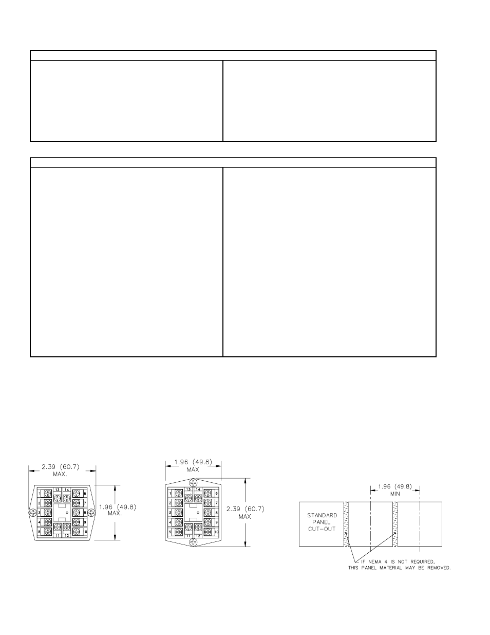
MULTIPLE UNIT STACKING
The C48T is designed for close spacing of multiple units. Units can be
stacked either horizontally or vertically. For vertical stacking, install the panel
latch with the screws to the sides of the unit. For horizontal stacking, the panel
latch screws should be at the top and bottom of the unit. The minimum spacing
from center line to center line of the units is 1.96" (49.8 mm). This spacing is
the same for vertical or horizontal stacking.
Note: When stacking units, provide adequate panel ventilation to ensure that the
maximum operating temperature range is not exceeded.
PANEL CUT-OUT SPACING FOR MULTIPLE UNIT STACKING.
HORIZONTAL ARRANGEMENT SHOWN.
PANEL LATCH INSTALLED FOR VERTICAL
UNIT STACKING
PANEL LATCH INSTALLED FOR
HORIZONTAL UNIT STACKING