Mot or drive, Ordering information follower mode application, Mo tor – Red Lion MDC User Manual
Page 4: Master mode application, Operator access, User settings, Program diagnostics, Program security
4
OPERATOR ACCESS
This is used with the program disable DIP switch or an external user input
that is selected for the program disable function. When a setpoint is selected as
NO, it can be viewed, but NOT changed from the front panel keypad. The
following setpoint values can be disabled from front panel access programming:
Speed/Ratio Setpoint 1 and 2
Jog Speed
Ramp Rate 1 and 2
Jog Ramp
Alarm Setpoint 1 and 2
Gain
Setpoint Scroll Menu
USER SETTINGS
The operator can reset ALL parameters to the factory settings if desired.
PROGRAM DIAGNOSTICS
This allows testing of the various MDC inputs and outputs. It is especially
useful after unit installation to independently test the operation of external
switches, relays, the feedback transducer, and the motor drive system.
Inputs - The MDC displays an alphanumeric character to indicate a Dedicated
Function Input or a User Input is active. This allows the user to check switch
operation and wiring connections to the Inputs.
Alarm Outputs - The up and down arrow keys are used to select an alarm
output and set it to the active or inactive state. This allows the user to check
the operation of devices wired to the alarm outputs and the wiring
connections.
Drive Output - This function allows the user to test the Drive System. A %
Output value is entered through the front panel keypad causing the motor to
run at the corresponding open loop speed. The display indicates the motor’s
feedback frequency.
PROGRAM SECURITY
The programmable code number is used in conjunction with the program
disable DIP switch and/or a user input programmed for the program disable
function to limit operator access to programming.
ORDERING INFORMATION
FOLLOWER MODE APPLICATION
A fertilizer production facility is mixing pellets containing Nitrogen with
pellets that contain Phosphorus. A chemical ratio of 1:1 is determined by the
speed of two different conveyors. Because of differences in the gearing of
the conveyor and concentration of the pellets, the Nitrogen conveyor motor
must run at 3 times the speed of the Phosphorus conveyor motor in order to
produce a 1:1 mixture. The maximum speed of both motors is 2000 RPM.
Set the follower MDC scaling to produce a 1:1 mixture of Nitrogen and
Phosphorus when a setpoint of 1.0000 is entered. Display speed units are in
RPM’s. Both the lead and feedback frequency are taken from 60 tooth gears
on each motor shaft.
1) Choose the Phosphorus conveyor motor for the follower MDC. It runs
slower than the Nitrogen conveyor motor.
2) Set the Pulses per revolution feedback to 60.
3) Set the MAX RPM feedback to 2000. This is the conveyor motor’s
maximum operating speed.
4) Set display decimal point to 0.
5) Set display unit to 2000. The display speed unit maximum is 2000 at a
MAX RPM FB of 2000. If the display units wanted were conveyor feet/
minute or Phosphorus pellets in lbs/sec, the equivalent display value for
2000 RPM would be entered.
6) Set the pulses per revolution lead to 60.
7) Setting the MAX RPM Lead:
This is the Lead RPM that would be necessary to have a 1:1 mixture if
the Follower Speed was MAX RPM FB (2000 RPM). Since the Nitrogen
conveyor motor must run 3 times as fast as the Phosphorus motor, MAX
RPM LD = 3 * 2000 = 6000 RPM. Set MAX RPM LD = 6000 RPM. This
is the correct value, even though the Nitrogen conveyor motor would never
actually run at 6000 RPM. A ratio setpoint of 1.0000 on the MDC is now
equal to a 1:1 mixture of Phosphorus and Nitrogen.
OPEN LOOP
JO
G
F-ST
OP
R-ST
OP
RUN
USR.IN
P.
4
USR.IN
P.
3
USR.IN
P.
2
COMM.
FEEDBACK IN
P
LEAD IN
P
4
3
2
1
12
11
10
9
8
7
6
5
-
+
RE
F.
COMM.
DRIVE ENABLE OU
T
AL-2 SN
K
RE
D
AL-1 SN
K
COMM.
+12VDC OU
T
LABEL
)
(SEE SIDE
AC PW
R
10 11
6 7 8 9
4
3
2
1
5
ISOL
AT
ED
DRIVE OUTPUT
USR.IN
P.
1
MO
TOR
WHITE
BLAC
K
EMERGENCY
STOP
STOP
MOTOR
START
MOTOR
MOT
OR
DRIVE
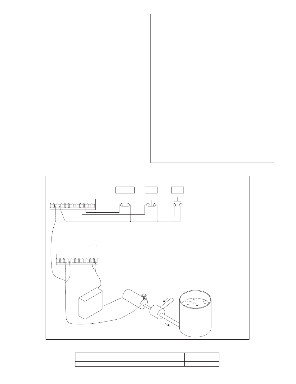
MASTER MODE APPLICATION
A pump delivers a maximum of 30.0 gallons per minute with a shaft speed of
1750 RPM. A shaft pulse encoder generates 60 pulses/revolution. Set the MDC
scaling to control and display pumping speed in tenths of a gallon/minute. In the
Program Scaling Module:
1) Set the pulses per revolution feedback to 60.
2) Set the maximum RPM feedback to 1750. This is the pump shaft’s maximum
operating speed.
3) Set display decimal point to 0.0. Display units are in 0.1 gpm.
4) Set max display units to 30.0. The display speed unit maximum is 30.0 at a MAX
RPM FB of 1750.
MODEL NO.
DESCRIPTION
PART NUMBERS
115/230VAC
MDC
Motor Drive Controller with Red Backlighting
MDC00100