Description (cont’d), Safety summary, Specifications – Red Lion MDC User Manual
Page 2: Programming
2
DESCRIPTION (Cont’d)
The unit is factory configured for an isolated 0 to 10 VDC drive output
signal. The output drive signal can be adjusted to span from 0 to 15 VDC via an
accessible potentiometer. The drive output is jumper selectable for an external
reference. To use the external reference, the MDC is connected to the drive in
place of an external potentiometer.
The Motor Drive Controller has a light weight, high impact plastic case with a
clear viewing window. The sealed front panel meets NEMA 4X/IP65 specifications
for wash-down and/or dusty environments, when properly installed. Plug-in style
terminal blocks simplify installation and wiring change-outs.
SAFETY SUMMARY
All safety related regulations, local codes and instructions that appear in the
manual or on equipment must be observed to ensure personal safety and to
prevent damage to either the instrument or equipment connected to it. If
equipment is used in a manner not specified by the manufacturer, the protection
provided by the equipment may be impaired.
Do not use this unit to directly command motors, valves, or other actuators
not equipped with safeguards. To do so, can be potentially harmful to persons
or equipment in the event of a fault to the unit.
SPECIFICATIONS:
1. DISPLAY: 2x8, 0.3" (7 mm) high characters, negative image transmissive
LCD, with red LED backlighting.
2. POWER: 115/230 VAC ±10%, 50/60 Hz, 10 VA, switch selectable.
3. MEMORY: Non-volatile E
2
PROM retains all programming information and
values when power is removed or interrupted.
Power Cycles(ON/OFF): 100,000 min.
Data Retention: 10 years min.
4. SENSOR POWER: +12 VDC ±25% @ 100 mA.
5. INPUTS (LEAD AND FEEDBACK): DIP Switch selectable to accept input
pulses from a variety of sources including outputs from CMOS or TTL
circuits and all standard RLC sensors.
Input Freq:
1 Hz to 20 KHz (Master Mode), 1 Hz to 12 KHz (Follower Mode).
Logic: Input trigger levels V
IL
= 1.5 V
MAX
; V
IH
= 3.75 V
MIN
.
Current Sinking: Internal 7.8 KΩ pull-up to +12 VDC, I
MAX
= 1.6 mA.
Current Sourcing: Internal 3.9 KΩ pull-down, 7.3 mA @ 28 VDC
MAX
.
Magnetic Pickup:
Sensitivity: 200 mV PEAK.
Hysteresis: 100 mV.
Input impedance: 3.9 KΩ @ 60 Hz.
Maximum input voltage: ±50 V PEAK.
Note: For magnetic pickup input, the Sink/Source DIP switch must be in the
SRC position.
6. CONTROL LOOP RESPONSE: 10 msec (Master Mode), 20 msec
(Follower Mode).
7. CONTROL ACCURACY:
0.01% of Speed Setpoint (Master Mode)
0.02% of Ratio Setpoint (Follower Mode)
Minimum Frequency Resolution: 0.00125 Hz
8. ERROR TRIM: ±4095 BITS.
9. ERROR GAIN: 0 to 99%.
10. RAMP RATE: (Ramp 1, Ramp 2, and Jog Ramp)
1 Hz to 20 KHz/sec, set in user units/sec.
0.0001 to 1.9999 ratio units/sec (Ramp 1 & 2 in Follower Mode).
11. CONTROL INPUTS:
Internal 10 KΩ pull-up to +5 VDC. V
IL
= 1.0 V
MAX
, V
IH
= 4.0 V
MIN
.
Response time = 10 msec nominal, 30 msec max.
INPUTS
SWITCH CONNECTIONS
RUN
Momentary N.O.
FAST STOP
Momentary N.C.
RAMP STOP
Momentary N.C.
JOG
Sustained N.O.
OPEN LOOP
Maintained
USER INPUTS(4)
Function Specific
12. OUTPUTS:
Drive Enable, Alarm 1, and Alarm 2:
Solid state, current sinking NPN Open collector transistor.
V
CE
= 1.1 V
SAT
@ 100 mA max.,
V
OH
= 30 VDC max.
(Internal zener diode protection.)
Response Time:
Drive Enable: 10 msec nominal; 30 msec max.
Alarm 1&2: Programmable
Normal: 1 sec nominal, 2 sec max.
Fast: 20 msec nominal, 40 msec max.
Isolated Drive Output: Jumper selectable internal/external reference 5 mA max.
Internal Reference: Pot adjustable from 0 to 5 VDC min. through 0 to 15
VDC max. span.
External Reference: 15 VDC max. (positive polarity only).
Isolation: 2300 Vrms for 1 minute
250 V working
13. ENVIRONMENTAL CONDITIONS:
Operating Temperature: 0 to 50°C
Storage Temperature: -40 to 70°C
Operating and Storage Humidity: 85% max. RH (non-condensing) from
0°C to 50°C.
Altitude: Up to 2000 meters
14. CONSTRUCTION: High impact plastic case with clear viewing window.
The front panel meets NEMA4 X/IP65 requirements for indoor use when
properly installed. Installation Category II, Pollution Degree 2. Panel gasket
and mounting clips included.
15. WEIGHT: 1.5 lbs. (0.68 Kg).
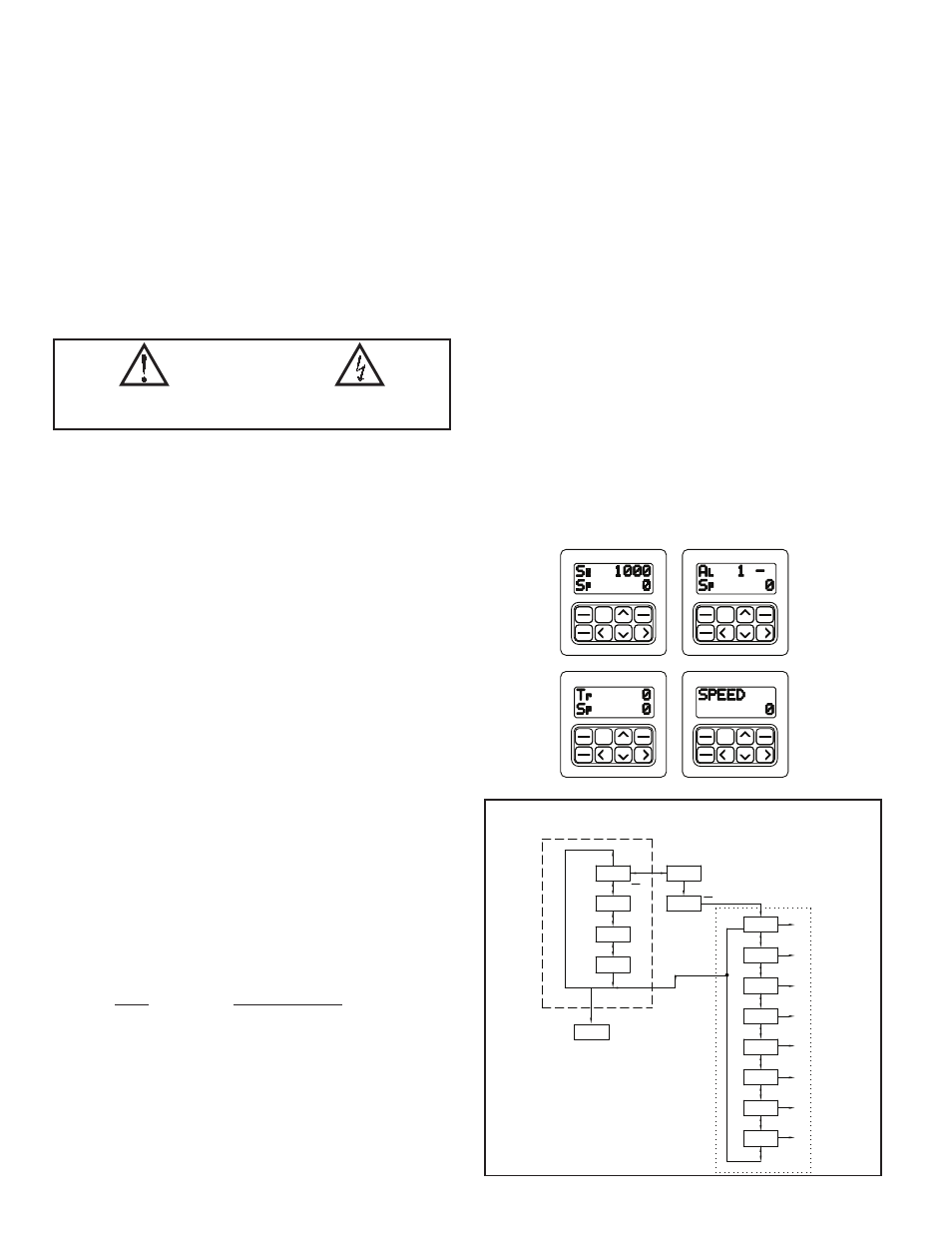
PROGRAMMING
Programming the MDC unit is accomplished through the front panel keypad,
which allows the user to enter into Main Menus, Sub-Menus, and Edit Menus.
The English language prompts, the flashing parameter values, and the front panel
keypad aid the operator during programming. In the normal run mode, the main
display loop allows the user to scroll through the four programmable indication
displays, using the direction keys. From the main loop, setpoints, alarm values
and a gain value may be accessed directly for changes, without entering the
programming loop. All other parameters are accessed through the pro-gramming
loop, which can be set to require an access code number for loop entry. In the
programming loop, parameters can be viewed or changed and the operator can
exit anywhere in the loop.
SET
PGM
ENT
RUN
F1
SEL
ESC
F2
STP
STP
F2
ESC
SEL
F1
RUN
ENT
PGM
SET
STP
F2
ESC
SEL
F1
RUN
ENT
PGM
SET
STP
F2
ESC
SEL
F1
RUN
ENT
PGM
SET
102
Sp
RUN
- -
Sp
500
p
S
1 1
>
>
>
>
>
>
>
ENT
PGM
ENT
ALARMS
4
3
2
1
0
** *
>
>
>
>
>
>
>
>
SET
ESC
<
>
PGM
>
>
>
>>
>
>
>
>
SEL
>
SEL
>
SEL
>
SEL
>
SEL
>
SEL
>
SEL
>
SEL
>
SEL
OPTIONS
SECURITY
PROGRAM
DIAGNOST
PROGRAM
DISPLAY
PROGRAM
PROGRAM
USER
PROGRAM
PROGRAM
SCALING
PROGRAM
MODE
MASTER
0000
PRO.CODE
500
Tr
PROGRAM
MODE
AL
S R
500
500
SPEED
USER
SETPOINTS
>
>
*** - ACTIVE ONLY WHEN THE PROGRAM
DISABLE FUNCTION IS ENABLED.
1-4 - THE FOUR INDICATION DISPLAYS
--DASHED LINE:
MAIN DISPLAY LOOP
... DOTTED LINE:
PROGRAMMING LOOP
<
ESC
INDICATION DISPLAY
PROGRAMMING
MODULE
MODULE
CAUTION: Risk of Danger.
Read complete instructions prior to
installation and operation of the unit.
CAUTION: Risk of electric shock.