Rogramming, Eter – Red Lion PAXLTC User Manual
Page 6
This parameter sets the amount of digital filtering applied to the input signal.
If the temperature display is difficult to read due to small variations or noise,
increased levels of filtering will help to stabilize the display. Although the
digital filter features a “moving window” to help minimize response time,
higher levels of filtering will result in slightly longer response times.
Set the desired level of input filtering by pressing the up or down arrow keys.
Press the PAR key to save the selection and advance to the next parameter.
-
normal filtering
-
maximum filtering
DECIMAL POINT POSITION
TEMPERATURE DISPLAY OFFSET
DIGITAL FILTERING
THERMOCOUPLE TYPE
6
TEMPERATURE SCALE
to
-
no digital filtering
-
increased filtering
R
SELECTION
TC TYPE
TC TYPE
SELECTION
mV indicator
N
K
B
S
J
E
T
Select the thermocouple type by pressing the arrow keys ( or ) to sequence
through the selection list. When the desired selection is displayed, press the PAR
key to save the selection and advance to the next parameter. Refer to the
thermocouple range and accuracy specification for additional TC information.
Select the desired temperature scale by pressing the up or down arrow keys.
This setting does not change the Custom Units Overlay display (if installed).
Press the PAR key to save the selection and advance to the next parameter.
Select the decimal point position by pressing the up or down arrow keys.
This sets the display resolution to 1 or 0.1 degree. This parameter is not
available for thermocouple types R, S and B, where the display resolution is
always 1 degree. When mV indicator mode is selected for thermocouple type,
the display resolution is fixed at 0.01 mV (10
V).
Press the PAR key to save the selection and advance to the next parameter.
The temperature display can be corrected with an offset value. This can be used
to compensate for probe errors or errors due to variances in probe placement, or
to adjust the readout to a reference thermometer. Set the desired display offset
value by pressing (and/or holding) the up or down arrow keys. When the desired
offset value is displayed, press the PAR key to save the selection and advance to
the next parameter. The display resolution for the offset value is the same as the
decimal point position programmed above. The display offset is not available
when mV indicator mode is selected for thermocouple type.
When the Input display is above the present HI value or below the present
LO value for the entered delay time, the meter will capture the Input display as
the new HI or LO reading. A delay time helps to avoid false captures of sudden
short spikes or Input display variations that may occur during start-up.
Set the desired capture delay time by pressing the up or down arrow keys.
Press the PAR key to save the selection and advance to the next parameter.
PEAK (HI)/ VALLEY (LO) CAPTURE DELAY TIME
seconds
tYPE
Thermocouple
Type
PAR
Temperature
Scale
SCAL
PAR
Digital Input
Filtering
FLtr
PAR
PAR
TEMPERATURE
DISPLAY
Pro
Decimal
Point Position
PAR
dCPt
OFSt
Temperature
Display Offset
PAR
Peak/Valley
Capture Time
HL-t
PAR
Units Label
Backlight
bLIt
PAR
PAR
Calibration
Mode Entry
CAL
End
TEMPERATURE
DISPLAY
4.0 P
ROGRAMMING
THE
M
ETER
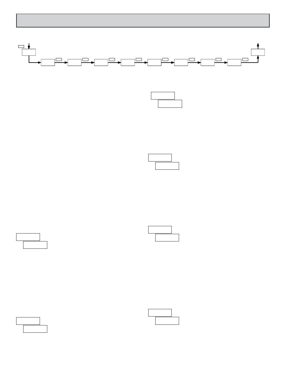
PROGRAMMING SEQUENCE
The Thermocouple Meter has up to seven programmable parameters that are
entered in the sequence shown above, using the front panel push buttons.
Depending on the thermocouple type selected, some parameters are not
applicable and are bypassed in the sequence.
The last programming step offers the choice of entering calibration mode.
From this mode, the user can restore the meter to factory default settings, or
recalibrate the signal input and cold junction temperature if necessary. To
prevent inadvertent entries, an access code must be keyed-in to perform any
operations in calibration mode.
Note: Programming mode can be locked out using the Program Disable input
terminal. With the PGM.DIS. terminal connected to COMM, the meter displays
“
” when the PAR key is pressed, and will not enter programming mode.
PROGRAMMING MODE ENTRY
Press the PAR key to enter Programming Mode. The meter briefly displays
followed by the first programming parameter described below.
PROGRAMMING MODE TIMEOUT
The Programming Mode has an automatic time out feature. If no keypad
activity is detected for approximately 60 seconds, the meter automatically exits
Programming Mode. The meter briefly displays
and returns to the normal
display mode. When automatic timeout occurs, any changes that were made to
the parameter currently being programmed will not be saved.
PROGRAMMING PARAMETERS
In Programming Mode, the display alternates between the parameter and the
current selection or value for that parameter. The dual display with arrows is
used below to illustrate the alternating display. The selection choices or value
range for each parameter is shown to the right of the alternating display.