Iring, Eter, Nstalling – Red Lion PAXLTC User Manual
Page 4
4
2.0 W
IRING
THE
M
ETER
1.0 I
NSTALLING
THE
M
ETER
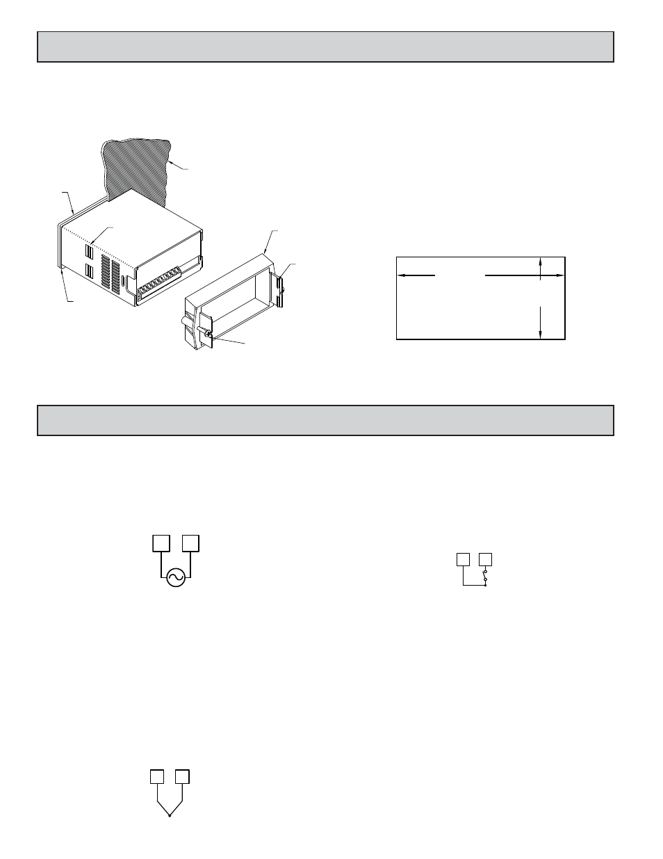
Installation
The PAX meets NEMA 4X/IP65 requirements when properly installed. The
unit is intended to be mounted into an enclosed panel. Prepare the panel cutout
to the dimensions shown. Remove the panel latch from the unit. Slide the panel
gasket over the rear of the unit to the back of the bezel. The unit should be
installed fully assembled. Insert the unit into the panel cutout.
While holding the unit in place, push the panel latch over the rear of the unit
so that the tabs of the panel latch engage in the slots on the case. The panel latch
should be engaged in the farthest forward slot possible. To achieve a proper seal,
tighten the latch screws evenly until the unit is snug in the panel (Torque to
approximately 7 in-lbs [79N-cm]). Do not over-tighten the screws.
Installation Environment
The unit should be installed in a location that does not exceed the maximum
operating temperature and provides good air circulation. Placing the unit near
devices that generate excessive heat should be avoided.
The bezel should be cleaned only with a soft cloth and neutral soap product.
Do NOT use solvents. Continuous exposure to direct sunlight may accelerate the
aging process of the bezel.
Do not use tools of any kind (screwdrivers, pens, pencils, etc.) to operate the
keypad of the unit.
-.00
(92 )
-.0
+.8
3.62
+.03
(45 )
1.77
-.0
+.5
-.00
+.02
PANEL CUT-OUT
LATCHING
TABS
PANEL
LATCH
PANEL
MOUNTING
SCREWS
LATCHING
SLOTS
PANEL
GASKET
BEZEL
PANEL
POWER WIRING
Primary AC power is connected to Terminals 1 and 2. To reduce the chance of
noise spikes entering the AC line and affecting the indicator, the AC power should
be relatively “clean” and within the specified limits. Drawing power from heavily
loaded circuits or circuits which also power loads that cycle on and off,
(contactors, relays, motors, machinery, etc.) should be avoided.
SIGNAL WIRING (TC SENSOR)
Remove power and connect the negative thermocouple lead (always red) to
TC- (Terminal 6) and the positive lead to TC+ (Terminal 5). Be certain that
connections are clean and tight. If the thermocouple probe is to be mounted
away from the meter, thermocouple extension grade wire must be used (copper
wire will not work). Use the correct type and observe the correct polarity.
Always refer to the sensor manufacturer’s instructions for probe wiring
connections, if available. For multi-probe temperature averaging applications,
two or more thermocouple probes may be connected at the meter. (Always use
the same type.) In order to minimize the chances of coupling noise into the
wires and subsequently causing bouncy and erroneous readings, proper
guidelines for thermocouple wire routing must be followed.
PROGRAM DISABLE INPUT WIRING
PGM.DIS. (Terminal 3) is a digital input that is active when connected to
Comm (Terminal 4). Any form of mechanical switch or current sinking logic with
less than 0.7 V saturation may be used. The use of shielded cable is recommended.
Follow the EMC Installation Guidelines for shield connection.
WIRING OVERVIEW
Electrical connections are made via screw-clamp terminals located on the
back of the meter. All conductors should conform to the meter’s voltage and
current ratings. All cabling should conform to appropriate standards of good
installation, local codes and regulations. It is recommended that the power
supplied to the meter be protected by a fuse or circuit breaker.
When wiring the meter, compare the numbers embossed on the back of the
meter case against those shown in wiring drawings for proper wire position. Strip
the wire, leaving approximately 0.3" (7.5 mm) bare lead exposed (stranded wires
should be tinned with solder). Insert the lead under the correct screw-clamp
terminal and tighten until the wire is secure. (Pull wire to verify tightness.)
1
2
AC
AC
AC Power
Terminal 1: VAC
Terminal 2: VAC
5
6
+
-
TC+
TC-
COMM
PGM.DIS.
3
4
Thermocouple