Rear panel dip switches, Timebase selection, Typical application – Red Lion DT8 User Manual
Page 3: Conveyor belt speed indicator
3
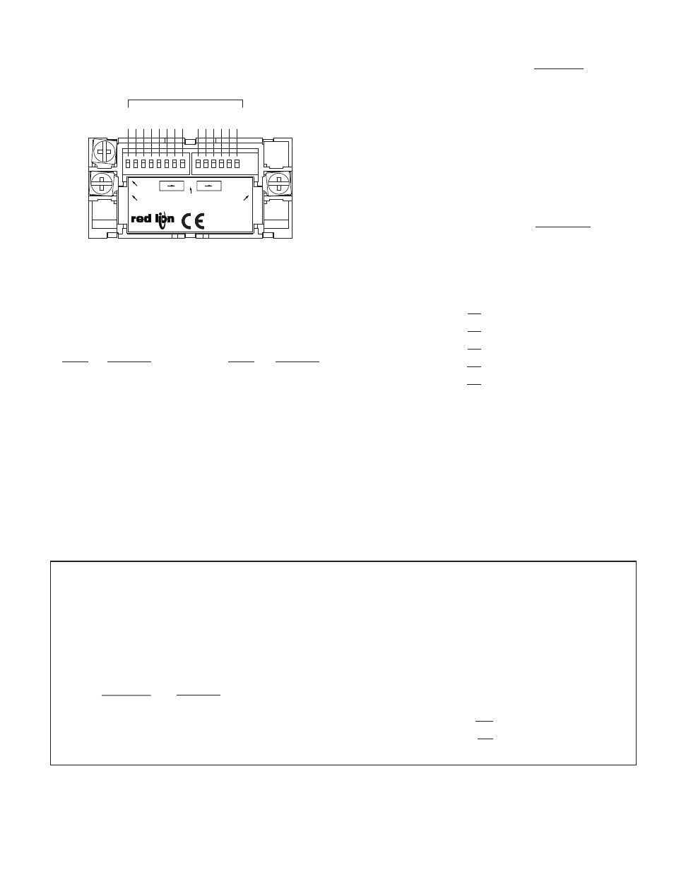
REAR PANEL DIP SWITCHES
When viewing the Ditak 8 from the rear, there are two banks of DIP switches
located along the top edge of the PC board. The bank of eight switches to the
left is labeled SWA and the bank of six switches to the right is labeled SWB. All
of the switches are used to select the desired Timebase.
WARNING: Lithium battery may explode if incinerated.
TIMEBASE SELECTION
The Ditak 8 has a Timebase selection range from 3.906 msec to 63.99 sec.
SWA 1 is set to the “ON” position for the minimum Timebase setting. SWA 1
through SWB 6 are set to the “ON” position for the maximum Timebase setting.
A specific Timebase setting is achieved by adding the appropriate individual
Timebase increments.
SWITCH
TIMEBASE
INCREMENTS
SWITCH
TIMEBASE
INCREMENTS
SWA 1
1
SWB 1
256
SWA 2
2
SWB 2
512
SWA 3
4
SWB 3
1024
SWA 4
8
SWB 4
2048
SWA 5
16
SWB 5
4096
SWA 6
32
SWB 6
8192
SWA 7
64
SWA 8
128
1
2
4
8
16
32
64
128
256
512
1024
2048
4096
8192
TIMEBASE INCREMENTS
V+ 2
3 INP
1 GND
SWB
8
1
ON
SWA
DT8
1
6
WARNING: LITHIUM BATTERY
MAY EXPLODE IF INCINERATED
MADE IN U.S.A.
YORK, PA.
The Timebase increment total is computed according to the following formula:
TIMEBASE INCREMENT TOTAL (TBIT) =
WHERE:
DR
=
Desired Reading
RPM
=
Revolutions Per Minute
PPR
=
Pulses Per Revolution
Example: Find the appropriate Timebase DIP switch setting for desired
parameters.
Desired Readout (DR)
= 2500
Revolutions Per Minute (RPM) = 1250
Pulses Per Revolution (PPR)
= 50
TIMEBASE INCREMENT TOTAL (TBIT) =
TBIT = 614.44
TBIT = 614
{round to the nearest whole number}
TBIT = 614
DIP SWB 2
-
512
102
-
Needed
DIP SWA 7
-
64
38
-
Needed
DIP SWA 6
-
32
6
-
Needed
DIP SWA 3
-
4
2
-
Needed
DIP SWA 2
-
2
0
-
Needed
Note: If no timebase switches are turned on, the Ditak 8 will default to 3.906
msec timebase.
DIP switches SWA 2, 3, 6, 7, and SWB 2 are all set to the “ON” position for
a Timebase Increment Total of 614. If it is desired to know what the
approximate Timebase is in seconds, use the following formula:
TBIT x 0.003906
= Time in seconds
614 x 0.003906
= 2.398 sec.
2500 x 15,361
1250 x 50
DR x 15,361
RPM x PPR
TYPICAL APPLICATION
CONVEYOR BELT SPEED INDICATOR
It is desired to display the rate of a conveyor belt used to carry PC Boards through an infrared soldering chamber that is variable from 0 to 10 feet per minute.
The rate must be adjusted depending on the size of the boards being soldered. The display of the rate indicator must read in feet per minute. The shaft of the variable
speed motor contains a keyway. A speed of 100 RPM will produce a belt speed of 10 ft/min. A proximity sensor is used to monitor the speed of the shaft. The Ditak
8 can be used to display the belt speed in this application. The output signal of the sensor is connected to the Ditak 8 Terminal 3 (INP). The sensor common and
shield are connected to the Ditak 8 Terminal 1 (GND). The Timebase setting is to be determined by using the formula.
TIMEBASE INCREMENT TOTAL (TBIT) =
=
Desired Reading
=
10
MAX RPM Of Shaft
=
100
Pulses Per Revolution
=
1
TBIT = 1536.1
TBIT = 1536
{round to the nearest whole number}
TBIT = 1536
DIP SWB 3
- 1024
512
-
Needed
DIP SWB 2
-
512
0
-
Needed
10 x 15,361
100 x 1
DR x 15,361
RPM x PPR