Specifications (cont'd), Emc installation guidelines, Wiring connections – Red Lion DT8 User Manual
Page 2: Block diagram, Logic pulse inputs from other circuits & sensors, Mp62ta
2
SPECIFICATIONS (Cont'd)
8. CERTIFICATIONS AND COMPLIANCES:
SAFETY
IEC 1010-1, EN 61010-1: Safety requirements for electrical equipment for
measurement, control, and laboratory use, Part 1.
IP65 Enclosure rating (Face only), IEC 529
Type 4X Enclosure rating (Face only), UL50
ELECTROMAGNETIC COMPATIBILITY
Emissions and Immunity to EN 61326: 2006: Electrical Equipment for
Measurement, Control and Laboratory use.
Immunity to Industrial Locations:
Electrostatic discharge
EN 61000-4-2 Criterion A
4 kV contact discharge
8 kV air discharge
Electromagnetic RF fields
EN 61000-4-3 Criterion A
10 V/m (80 MHz to 1 GHz)
3 V/m (1.4 GHz to 2 GHz)
1 V/m (2 GHz to 2.7 GHz)
Fast transients (burst)
EN 61000-4-4 Criterion A
power 2 kV
I/O signal 1 kV
Surge
EN 61000-4-5 Criterion A
power 1 kV L to L, 2 kV L to G
RF conducted interference
EN 61000-4-6 Criterion A
3 V/rms
Power frequency magnetic fields EN 61000-4-8 Criterion A
30 A/m
AC power
EN 61000-4-11 Criterion A
Voltage dip
0% during 1 cycle
40% during 10/12 cycle
70% during 25/30 cycle
Short interruptions
Criterion B
0% during 250/300 cycles
Emissions:
Emissions
EN 55011
Class B
Notes:
1. Criterion A: Normal operation within specified limits.
2. Criterion B: Temporary loss of performance from which the unit self-
recovers.
Refer to the EMC Installation Guidelines section of this bulletin for additional
information.
9. WEIGHT: 3.4 oz (96.4 g)
EMC INSTALLATION GUIDELINES
Although this unit is designed with a high degree of immunity to
ElectroMagnetic Interference (EMI), proper installation and wiring methods
must be followed to ensure compatibility in each application. The type of the
electrical noise, source or coupling method into the unit may be different for
various installations. In extremely high EMI environments, additional measures
may be needed. Cable length, routing and shield termination are very important
and can mean the difference between a successful or a troublesome installation.
Listed below are some EMC guidelines for successful installation in an
industrial environment.
1. Use shielded (screened) cables for all Signal and Control inputs. The shield
(screen) pigtail connection should be made as short as possible. The
connection point for the shield depends somewhat upon the application.
Listed below are the recommended methods of connecting the shield, in order
of their effectiveness.
a. Connect the shield only at the panel where the unit is mounted to earth
ground (protective earth).
b. Connect the shield to earth ground at both ends of the cable, usually when
the noise source frequency is above 1 MHz.
c. Connect the shield to common of the unit and leave the other end of the
shield unconnected and insulated from earth ground.
2. Never run Signal or Control cables in the same conduit or raceway with AC
power lines, conductors feeding motors, solenoids, SCR controls, and
heaters, etc. The cables should be run in metal conduit that is properly
grounded. This is especially useful in applications where cable runs are long
and portable two-way radios are used in close proximity or if the installation
is near a commercial radio transmitter.
3. Signal or Control cables within an enclosure should be routed as far away as
possible from contactors, control relays, transformers, and other noisy
components.
4. In extremely high EMI environments, the use of external EMI suppression
devices, such as ferrite suppression cores, is effective. Install them on Signal
and Control cables as close to the unit as possible. Loop the cable through the
core several times or use multiple cores on each cable for additional
protection. Install line filters on the power input cable to the unit to suppress
power line interference. Install them near the power entry point of the
enclosure. The following EMI suppression devices (or equivalent) are
recommended:
Ferrite Suppression Cores for signal and control cables:
Fair-Rite # 0443167251 (RLC #FCOR0000)
TDK # ZCAT3035-1330A
Steward #28B2029-0A0
Line Filters for input power cables:
Schaffner # FN610-1/07 (RLC #LFIL0000)
Schaffner # FN670-1.8/07
Corcom #1VR3
Note: Reference manufacturer’s instructions when installing a line filter.
5. Long cable runs are more susceptible to EMI pickup than short cable runs.
Therefore, keep cable runs as short as possible.
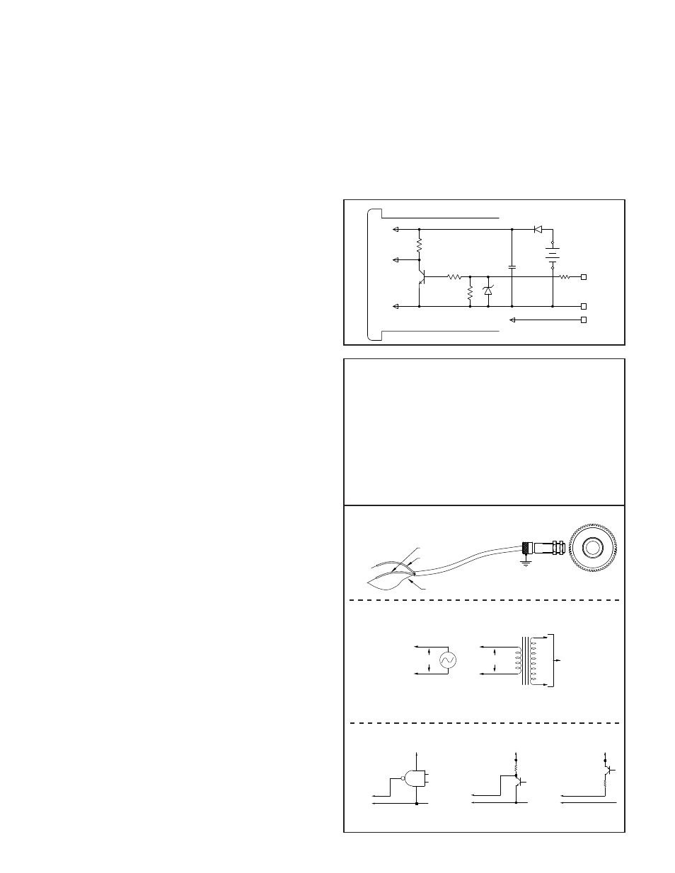
100K
100K
220K
3.6V
LITHIUM
3V
SIGNAL
GND
OPTIONAL
BACKLIGHTING
INP
GND
V+
6.2K
3
1
2
3.6V
.1µF
BLOCK DIAGRAM
WIRING CONNECTIONS
The electrical connections are made via rear screw-clamp terminals
located on the back of the unit. All conductors should meet voltage and
current ratings for each terminal. Also cabling should conform to appropriate
standards of good installation, local codes and regulations. It is recommended
that power supplied to the unit (AC or DC) be protected by a fuse or circuit
breaker. When wiring the unit, use the label to identify the wire position with
the proper function. Strip the wire, leaving approximately 1/4" bare wire
exposed (stranded wires should be tinned with solder). Insert the wire into
the screw-clamp terminal and tighten the screw until the wire is clamped
tightly. Each terminal can accept up to two #14 AWG wires.
The backlighting for a backlight version unit is powered between Terminal
2 (V+) and Terminal 1 (GND).
Variable Frequency AC Inputs, Signal Source Powered
Variable Frequency AC Inputs, Signal Source Powered
Minimum V
AC
for operation is 0.9 V peak.
Logic Pulse Inputs From Other Circuits & Sensors
SHIELD
RED
BLACK
COMM
INPUT
MACHINE
FRAME
MP62TA
AC
V
AUDIO OR A.C.
TACH. GEN.
SIGNAL SOURCE
INPUT
COMM
OR INVERTER
TRANSFORMER FOR
HIGH VOLTAGE
STEP-DOWN ISOLATION
AC
V
TO HIGH
POWER LINE
VOLTAGE
+V
INPUT
COMM
TTL or CMOS
INPUT
TRANSISTOR INPUT
NPN OPEN COLLECTOR
4.7K
+V
PNP OPEN COLLECTOR
TRANSISTOR INPUT
4.7K
COMMON
+V