Alibrating, Eter, Calibration procedure – Red Lion PAXLCL User Manual
Page 7: Calibration steps, Troubleshooting
7
5.0 C
ALIBRATING
THE
M
ETER
Direct calibration in the signal loop is usually not practical due to the
difficulty in varying the measured parameter and the confusing interaction that
occurs between span and offset adjustments. However, the PAXLCL can be
quickly and easily bench calibrated using a commercially available current
calibrator or the calibration set-up shown below.
CALIBRATION PROCEDURE
The procedure outlined below minimizes span/offset interaction and
simplifies calibration. In Steps 1 to 4 the unit is “nulled” to zero readout with
zero input signal current. In Steps 5 and 6, the span adjustments are made to
establish the required slope of the transfer curve. Then in Step 7, the transfer
curve is shifted up or down as required by setting the offset adjustments. In Step
8, the final “tweaking” adjustments are made at minimum and maximum signal
current. Setting the decimal points in Step 9 completes the calibration.
Before calibrating, the READOUT SPAN (Rs) and SWING CURRENT (Is)
must be determined.
WHERE:
Rs = (Max. Numerical Display) - (Min. Numerical Display) (Disregard Decimal Points)
Is = (Current @ Max. Display) - (Current @ Min. Display)
Example:
Readout is to be 0.00 @ 4 mA and 10.00 @ 20 mA.
READOUT SPAN (Rs) = 1000 - 0 = 1000
SWING CURRENT (Is) = 20 mA - 4 mA = 16
CALIBRATION STEPS
1. Power down the meter and remove it from its case. Turn off all offset and
span adjustment switches (S2-S10 down). S1 has no effect when zeroing
and can be in either position.
2. Turn the span control pot fully counter-clockwise (20 turns max.).
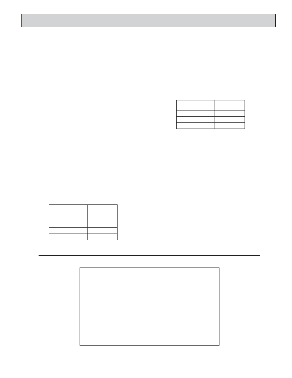
3. Turn on a combination of span adjust switches (6-10) to obtain a total value
closest to (but not greater than) the READOUT SPAN (Rs) desired (1000
in this example). The following chart gives an approximate span
adjustment value for each switch:
4. Place unit in its case and apply power. Apply zero current. Adjust the
indicator to read zero using the offset adjustment pot.
5. Apply the SWING CURRENT (Is) (16 mA in the example) to the input.
Set the exact READOUT SPAN value (1000) with span adj.pot.
6. Apply zero current to see if the zero value has shifted. If it has, re-zero with
the offset pot, then repeat Step 5.
7. After the span has been adjusted, set the signal current to the minimum
level (4 mA in the example). Record the meter reading (in this example the
reading will be 250). Subtract the desired reading at minimum current
value (0 in the example) from the recorded reading (0-250 = - 250). Power
down the meter and remove it from its case. Set the offset add/subtract
switch S1 (subtract = on), and the offset switches (S2-S5) to obtain a total
value closest to (but no more than) the difference between the desired
reading at minimum current value and the observed reading The following
chart gives an approximate offset adjustment value for each switch:
Place the meter in its case and apply power. Using the offset adjust pot,
adjust the readout to equal the desired reading at the minimum current
value (0 in the example).
8. Adjust the input signal current to its maximum value to see if the proper
readout is obtained (1000 @ 20 mA in the example). If the readout is
slightly off, adjust the span pot to obtain the true reading. Then, recheck
the reading at the minimum input current (4 mA) and readjust the offset
pot if necessary. Repeat the maximum and minimum readout adjustments
until the unit displays the proper readout at both extremes.
9. Set decimal points as desired using the three decimal point switches. The
unit can now be installed.
TROUBLESHOOTING
For further assistance, contact technical support at the appropriate company
numbers listed.
SWITCH NUMBER
SPAN VALUE
6
2100
7
1050
8
525
9
260
10
130
175
5
350
4
700
3
1400
2
OFFSET VALUE
SWITCH NUMBER
LIMITED WARRANTY
The Company warrants the products it manufactures against defects in materials and workmanship
for a period limited to two years from the date of shipment, provided the products have been stored,
handled, installed, and used under proper conditions. The Company’s liability under this limited
warranty shall extend only to the repair or replacement of a defective product, at The Company’s
option. The Company disclaims all liability for any affirmation, promise or representation with
respect to the products.
The customer agrees to hold Red Lion Controls harmless from, defend, and indemnify RLC
against damages, claims, and expenses arising out of subsequent sales of RLC products or products
containing components manufactured by RLC and based upon personal injuries, deaths, property
damage, lost profits, and other matters which Buyer, its employees, or sub-contractors are or may be
to any extent liable, including without limitation penalties imposed by the Consumer Product Safety
Act (P.L. 92-573) and liability imposed upon any person pursuant to the Magnuson-Moss Warranty
Act (P.L. 93-637), as now in effect or as amended hereafter.
No warranties expressed or implied are created with respect to The Company’s products except
those expressly contained herein. The Customer acknowledges the disclaimers and limitations
contained herein and relies on no other warranties or affirmations.