Etting, Witches, Iring – Red Lion PAXLCL User Manual
Page 4: Eter, Nstalling
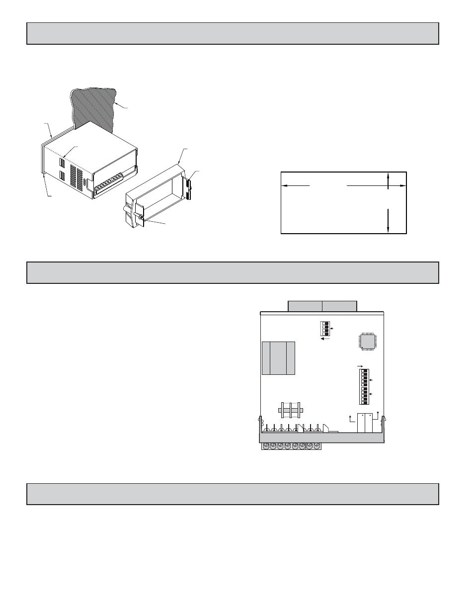
The meter has switches, which must be checked and/or changed prior to
applying power. To access the switches, remove the meter base from the case by
firmly squeezing and pulling back on the side rear finger tabs. This should lower
the latch below the case slot (which is located just in front of the finger tabs). It
is recommended to release the latch on one side, then start the other side latch.
Set-Up DIP Switches
Two banks of DIP switches are located inside the meter. The 10 position bank
of switches are used for calibrating the meter. The values of these switches are
discussed in section 5.0 Calibrating the Meter.
The bank of 4 switches located near the front display are used for the
selection of decimal points and backlight annunciator. Selecting “ON” position
enables the function.
4
2.0 S
ETTING
THE
S
WITCHES
3.0 W
IRING
THE
M
ETER
1.0 I
NSTALLING
THE
M
ETER
Installation
The PAX meets NEMA 4X/IP65 requirements when properly installed. The
unit is intended to be mounted into an enclosed panel. Prepare the panel cutout
to the dimensions shown. Remove the panel latch from the unit. Slide the panel
gasket over the rear of the unit to the back of the bezel. The unit should be
installed fully assembled. Insert the unit
into the panel cutout.
While holding the unit in place, push the panel latch over the rear of the unit
so that the tabs of the panel latch engage in the slots on the case. The panel latch
should be engaged in the farthest forward slot possible. To achieve a proper seal,
tighten the latch screws evenly until the unit is snug in the panel (Torque to
approximately 7 in-lbs [79N-cm]). Do not over-tighten the screws.
Installation Environment
The unit should be installed in a location that does not exceed the maximum
operating temperature and provides good air circulation. Placing the unit near
devices that generate excessive heat should be avoided.
The bezel should be cleaned only with a soft cloth and neutral soap product.
Do NOT use solvents. Continuous exposure to direct sunlight may accelerate the
aging process of the bezel.
-.00
(92 )
-.0
+.8
3.62
+.03
(45 )
1.77
-.0
+.5
-.00
+.02
PANEL CUT-OUT
LATCHING
TABS
PANEL
LATCH
PANEL
MOUNTING
SCREWS
LATCHING
SLOTS
PANEL
GASKET
BEZEL
PANEL
WIRING OVERVIEW
Electrical connections are made via screw-clamp terminals located on the
back of the meter. All conductors should conform to the meter’s voltage and
current ratings. All cabling should conform to appropriate standards of good
installation, local codes and regulations. It is recommended that power supplied
to the meter (AC) be protected by a fuse or circuit breaker.
When wiring the meter, compare the numbers embossed on the back of the
meter case against those shown in wiring drawings for proper wire position. Strip
the wire, leaving approximately 0.3" (7.5 mm) bare lead exposed (stranded wires
should be tinned with solder). Insert the lead under the correct screw-clamp
terminal and tighten until the wire is secure. (Pull wire to verify tightness.)
Main
Circuit
Board
D.P./ BACKLIGHT
REAR TERMINALS
FRONT DISPLAY
4
3
2
1
ON
OFFSET
SPAN
ON
1
2
3
4
5
6
7
8
9
10
OFFSET
SPAN
Backlight Annunciator for Units Label
4
Decimal Point 3 (0.000)
3
Decimal Point 2 (00.00)
2
Decimal Point 1 (000.0)
1
FUNCTION
SWITCH