Installation environment, Installation, Wiring connections – Red Lion CUB4V User Manual
Page 2: Decimal point selection
2
INSTALLATION ENVIRONMENT
The unit should be installed in a location that does not exceed the
maximum operating temperature and provides good air circulation.
Placing the unit near devices that generate excessive heat should be
avoided. The bezel should be cleaned only with a soft cloth and neutral
soap product. Do NOT use solvents.
Continuous exposure to direct sunlight may accelerate the aging
process of the bezel.
Do not use tools of any kind (screwdrivers, pens, pencils, etc.) to
operate the keypad of the unit.
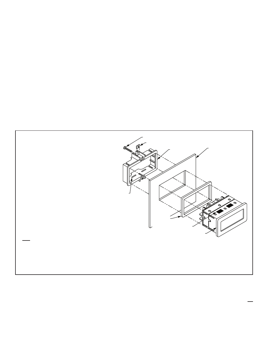
Installation
The CUB4 Volt and Current meters meet NEMA 4X/IP65
requirements for indoor use, when properly installed. The
units are intended to be mounted into an enclosed panel. A
sponge rubber gasket, mounting clip, two screws, and nut
fasteners are provided to install and seal the unit in the panel cutout.
The following procedure assures proper installation:
1. Cut panel opening to specified dimensions. Remove burrs and clean panel
opening.
2. Carefully remove center section of the panel gasket and discard. Slide
gasket over rear of the unit to the back of the bezel.
3. Slide nut fastener into slot on mounting clip and then insert mounting screw
through nut on both sides of mounting clip. Tip of mounting screw should
NOT project through hole on clip.
4. Install CUB4 unit through panel cutout.
5. Slide mounting clip over rear of unit until clip is against back of panel. The
mounting clip and CUB4 housing have a latching feature to hold the unit
in place until tightened.
Note: Hold the CUB4 front bezel in place when sliding the mounting clip into
position.
6. Alternately tighten each mounting screw to ensure uniform gasket pressure.
Visually inspect the gasket for proper seal. The gasket should be
compressed approximately 75 to 80% of its original thickness.
(Recommended torque is 28 to 36 in-oz.)
7. If the gasket is not adequately compressed and the mounting screws cannot
be tightened any further, loosen mounting screws and insure that the clip is
latched as close as possible to the panel.
8. Repeat step #6 for tightening the mounting screws.
5. ACCURACY: (@ 23°C, less than 85% RH)
D.C. Voltage: ±(0.1% + 1 digit)
D.C. Current:
199.9 µA, 1.999 mA, 19.99 mA ranges: ±(0.1% + 1 digit)
199.9 mA range: ±(0.15% + 1 digit)
6. OVERRANGE RATINGS, PROTECTION & INDICATION:
9 to 28 VDC power circuit is not isolated from the signal circuit.
Max Input Voltage:
0 to 199.9 mVDC Range: 75 VDC
All other voltage Ranges: 300 VDC
Max Input Current:
199.9 µA through 19.99 mA: 10 times max. range current
199.9 mA: 1 amp
Overrange Indication: Overrange is indicated by a “1” displayed in the
most significant digit and the blanking of the three least significant digits.
7. READING RATE: 2.5 readings per second
8. RESPONSE TIME: 1.5 seconds to settle for a step change
9. NORMAL MODE REJECTION: 60 dB 50/60 Hz
10. INPUT IMPEDANCE:
Voltmeter: 1 MΩ
Current Meter:
199.9 µA - 1 KΩ
19.99 mA - 10 Ω
1.999 mA - 100 Ω
199.9 mA - 1 Ω
11. CERTIFICATIONS AND COMPLIANCES:
CE Approved
EN 61326-1 Immunity to Industrial Locations
Emission CISPR 11 Class B
IEC/EN 61010-1
RoHS Compliant
UL Recognized Component: File #E179259
Type 4X Enclosure rating (Face only)
IP65 Enclosure rating (Face only)
IP20 Enclosure rating (Rear of unit)
Refer to EMC Installation Guidelines section of the bulletin for additional
information.
12. ENVIRONMENTAL CONDITIONS:
Operating Temperature: 0° to 60°C (above 50°C, derate backlight
operating voltage to 26 VDC maximum).
Storage Temperature: -40° to 80°C
Operating and Storage Humidity: 85% max relative humidity (non-
condensing) from 0 to 60°C.
Vibration to IEC 68-2-6: Operational 5-500 Hz, 5 g
Shock to IEC 68-2-27: Operational 30 g
Temperature Coefficient: 100 PPM/°C
Altitude: Up to 2000 meters.
13. CONSTRUCTION: High impact plastic case with clear viewing window.
(Panel gasket and mounting clip included.) This unit is rated for NEMA 4X/
IP65 indoor use. Installation Category II, Pollution Degree 2
14. WEIGHT: 3.3 oz. (93.5 g)
LATCHING
FEATURE
BEZEL
MOUNTING CLIP
NUT FASTENER
MOUNTING SCREW
GASKET
0.093" (2.4 mm)
THICK
LATCHING
FEATURE
EXISTING PANEL
.05" to .20"
(1.3 to 5.1mm)
THICK
WIRING CONNECTIONS
The electrical connections are made via screw-clamp terminals located on the
back of the unit. When wiring the unit, use the label to identify the wire position
with the proper function. All conductors should meet voltage and current ratings
for each terminal. Also cabling should conform to appropriate standards of good
installation, local codes and regulations. It is recommended that power supplied
to the unit be protected by a fuse or circuit breaker. Strip the wire, leaving
approximately ¼" bare wire exposed (stranded wires should be tinned with
solder). Insert the wire into the screw-clamp terminal and tighten the screw until
the wire is clamped tightly. Each terminal can accept up to two #14 AWG wires.
DECIMAL POINT SELECTION
The CUB4 Volt and Current Meters can be set-up to read in 10ths, 100ths, or
1000ths. The decimal point position is DIP switch selectable for one of three
locations. If all the DIP switches are set to the “OFF” position, then NO
decimal point will appear in the display. The DIP switches are located at the rear
of the unit.