Specifications – Red Lion GEMINI 42 User Manual
Page 2
2
SPECIFICATIONS
1.
DISPLAY: 6-Digit 0.56" (14.2 mm) High LED display
2. POWER REQUIREMENTS:
AC Versions:
AC Power: Switch selectable 115/230 VAC, (±10%), 50/60 Hz, 20 VA.
DC Power: 11 to 14 VDC @ 0.7 amp max.
3. SENSOR POWER: +12 VDC (±25%) @ 100 mA.
Note: The sensor supply voltage varies ±25% due to line and internal load
variations. All RLC sensors will accommodate this variation.
4. MEMORY: Non-volatile E
2
PROM memory retains all programming
information and count values (except Counter Load Values) when power is
removed or interrupted.
Power Cycles: 100,000 min.
Data Retention: 10 years min.
5. INPUTS 1 AND 2: Switch selectable to accept count pulses from a variety
of sources including switch contacts, outputs from CMOS or TTL circuits,
and all standard RLC sensors.
Current Sourcing: Unit provides 3.9 K
Ω
pull-down resistor for sensors with
current sourcing outputs. Max. input voltage = 28 VDC @ 7 mA.
Current Sinking: Unit provides 7.8 K
Ω
pull-up resistor for sensors with
current sinking outputs. Max. sensor current = 1.6 mA.
Debounce: Damping capacitor provides for switch contact debounce. Limits
count speed to 100 Hz max. with 50% duty cycle.
Lo Bias: Input trigger levels V
IL
= 1.5 V, V
IH
= 3.75 V.
Hi Bias: Input trigger levels V
IL
= 5.5 V, V
IH
= 7.5 V.
Note: Bias levels given are ±10% @ 12 VDC. These levels vary
proportionally with sensor supply voltage at “DC OUT” terminal.
6. MAGNETIC PICKUP INPUT:
Sensitivity: 150 mV peak (typical @ 12 VDC)
Hysteresis: 100 mV
Input Impedance: 26.5 K
Ω
@ 60 Hz
Maximum Input Voltage: ±50 V peak
7. RATE ACCURACY AND REPEATABILITY: 0.012%
8. RATE MINIMUM INPUT FREQUENCY: 0.03 Hz
Note: At frequencies below 0.03 Hz (1 pulse every 32 sec.) the rate display
will go to zero.
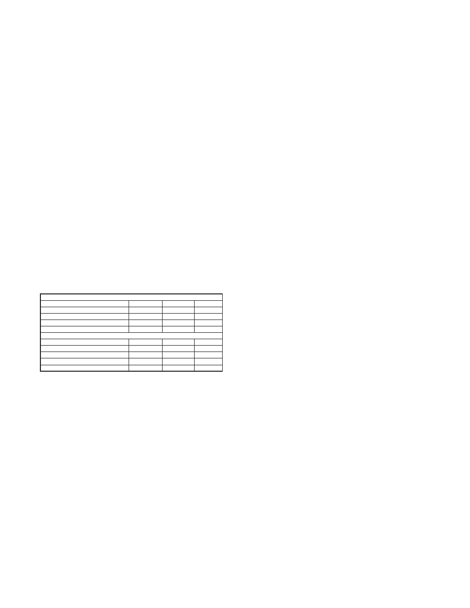
9. MAXIMUM COUNT RATES:
10. CONTROL INPUTS:
Reset: Active low (V
IL
= 1.5 V max.) internally pulled up to +12 VDC (I
SNK
= 3 mA), activation and de-activation response time = 10 msec.
Program Disable: Active low (V
IL
= 1.5 V max.) internally pulled up to +5
VDC (I
SNK
= 1 mA).
Print Request: Active low (V
IL
= 1.5 V max.) internally pulled up to +5
VDC (I
SNK
= 1 mA).
11. SERIAL COMMUNICATIONS (Optional):
Type: Bi-directional 20 mA current loop, 20 mA source provided. (Powers
up to 7 units in a loop with internal current source.)
Baud Rate: Programmable 300 to 2400
Maximum Address: 16 units. (Actual number in a single loop is limited by
serial hardware specifications.)
Data Format: 10 bit frame, Odd parity (one start bit, 7 data bits, one odd
parity bit, and one stop bit.)
Serial Hardware Specifications:
SO - Output Transistor Rating: V
MAX
= 30 VDC, V
SAT
= 1V
MAX
@ 20
mA.
SI - Input Diode Rating: V
F
= 1.25 V
TYP
; 1.5 V
MAX
.
Note: The compliance voltage rating of the source must be greater than the
sum of the voltage drops around the loop.
12. OUTPUT(S):
Solid-State: Current sinking NPN Open Collector Transistor(s). I
SNK
= 100
mA max. @ V
CE
= 1 V. V
OH
= 30 VDC max. (Internal Zener Diode
Protection).
Relays: Mounted on a field-replaceable PC board. Form C contacts rated at
5 amps @ 120/240 VAC, 28 VDC (resistive load), 1/8 H.P. @ 120 VAC
(inductive load). The operate time is 5 msec nominal and the release time
is 3 msec nominal.
Relay Life Expectancy: 100,000 cycles @ max. rating. (As load level
decreases, life expectancy increase.)
Programmed Timed Output: The timed output can be set from 0.01 to
599.99 seconds, ±(0.01% + 10 msec)
13. CERTIFICATIONS AND COMPLIANCES:
SAFETY:
IEC 1010-1, EN 61010-1: Safety requirements for electrical equipment for
measurement, control, and laboratory use, Part 1.
IP65 Enclosure rating (Face only), IEC 529
Type 4 Enclosure rating (Face only), UL50
ELECTROMAGNETIC COMPATIBILITY
Notes:
1. Metal bezel of unit connected with ground from rear bezel screw to metal
mounting panel.
2. When the unit is DC powered, a power line filter (RLC# LFIL0000 or
equivalent) was installed, so as not to impair the function of the unit.
Refer to the EMC Compliance Installation section of the manual for
additional information.
14. ENVIRONMENTAL CONDITIONS:
Operating Temperature: 0 to 50°C
Storage Temperature: -40 to 70°C
Operating and Storage Humidity: 85% max. relative humidity (non-
condensing) from 0°C to 50°C.
Altitude: Up to 2000 meters
15. CONSTRUCTION:
Metal die-cast bezel, plastic case. This unit is rated for NEMA 4/IP65 indoor
use. Installation Category II, Pollution Degree 2
16. WEIGHT: 2.1 lbs. (0.9 kg)
COUNTER/RATE MODE [41 1]
MODE
X1
X2
X4
Uni or Bi-directional
10 KHz
5 KHz
Anti-Coincidence Add/Subtract
4 KHz
2.5 KHz
Separate Input
8 KHz
4 KHz
Quadrature
5 KHz
4.5 KHz
2.5 KHz
MODE
DUAL COUNTER MODE [41 2]
X1
X2
X4
Uni or Bi-directional
9 KHz
4.5 KHz
Anti-Coincidence Add/Subtract
5 KHz
2.5 KHz
Quadrature
Separate Input
4.5 KHz
7.5 KHz
4 KHz
3.5 KHz
2.5 KHz
Immunity to EN 50082-2
Electrostatic discharge
EN 61000-4-2
Level 3; 8 Kv air
Electromagnetic RF fields
EN 61000-4-3
Level 3; 10 V/m
80 MHz - 1 GHz
Fast transients (burst)
EN 61000-4-4
Level 4; 2 Kv I/O
Level 3; 2 Kv power
2
RF conducted interference
EN 61000-4-6
Level 3; 10 V/rms
150 KHz - 80 MHz
EN 61000-4-8
Level 4; 30 A/m
Emissions to EN 50081-2
RF interference
EN 55011
Power mains class A
Enclosure class A
Power frequency magnetic fields
Level 2; 4 Kv contact
1