G3cn o, Nstalling, Ption – Red Lion G3CN User Manual
Page 2: Pecifications, Installation instructions, The option card label, Power supply requirements
2
1. POWER REQUIREMENTS:
Power is supplied to the option card from the main board of your G3 operator
interface.
2. COMMUNICATIONS:
CANopen Port: The CANopen port has format and baud rates that are
software programmable up to 1M baud and are digitally isolated. This port
may be configured for various CANopen protocols. Check www.redlion.
net/g3 for currently supported protocols.
Isolation from G3CN Communication ports to G3 operator interface:
1000 VDC for 1 minute.
3. ENVIRONMENTAL CONDITIONS:
Operating Temperature Range: 0 to 50°C
Storage Temperature Range: -20 to 80°C
Operating and Storage Humidity: 80% maximum relative humidity (non-
condensing) from 0 to 50°C.
Altitude: Up to 2000 meters.
4. CERTIFICATIONS AND COMPLIANCES:
ELECTROMAGNETIC COMPATIBILITY
Emissions and Immunity to EN 61326: Electrical Equipment for Measurement,
Control and Laboratory use.
Immunity to Industrial Locations: Reference G3 unit for emissions and
immunity specifications
5. CONSTRUCTION: Installation Category I, Pollution Degree 2.
6. INSTALLATION REQUIREMENTS: Card must be installed inside the
rear cover of a G3 operator interface with the hardware provided. See
“Installing the G3CN Option Card” for more details.
I
nstallIng
the
g3Cn O
ptIOn
C
ard
s
peCIfICatIOns
INSTALLATION INSTRUCTIONS
Each G3CN option card comes with a cable for communications and three
screws for attaching the option card to the inside of the G3 operator interface's
rear cover.
To install the option card, remove all power and I/O communications cables
from the unit. The G3 operator interface literature contains instructions for
removing the rear cover. Refer to the “Battery & Time Keeping” section.
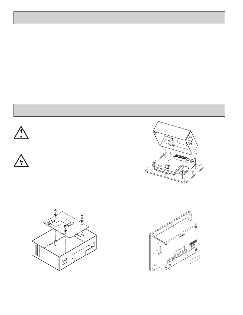
Using the three screws provided, connect the option card to the rear cover as
shown in Figure 1.
Connect the cable from the option card to CN11 on the main board of the G3
operator interface as shown in Figure 2. Be sure both ends of the cable are firmly
seated into their appropriate connector housings.
Carefully replace the rear cover by reversing the instructions for removing the
rear cover.
THE OPTION CARD LABEL
Place the option card label on your rear cover in the space indicated by the
dashed lines and labeled “COMMS EXPANSION MODULE.”
POWER SUPPLY REQUIREMENTS
NEW AND EXISTING INSTALLATIONS
The G3CN option card draws all of its power from the main board of your G3
operator interface. The specifications of your G3 operator interface account for
the power needs of an option card.
Figure 1
Figure 2
Caution: The option and main circuit boards contain static
sensitive components. Before handling the cards, discharge
static charges from your body by touching a grounded bare
metal object. Ideally, handle the cards at a static controlled clean
workstation. Also, handle the cards by the edges only. Dirt, oil,
or other contaminants that may contact the cards can adversely
affect circuit operation.
Warning: Depending upon the G3 operator interface, high voltage
may be present inside the operator interface. Be sure to remove
all power before removing the rear cover of the operator interface.
COMMS EXP
ANSION MODUL
E
RS232
RS485
RS232