Hardware, Hardware installation, Wiring – Red Lion GMSG1 Strain Gage Input Module User Manual
Page 4: Remove rubber module plug, Input range selection, Wiring connections
4
HARDWARE
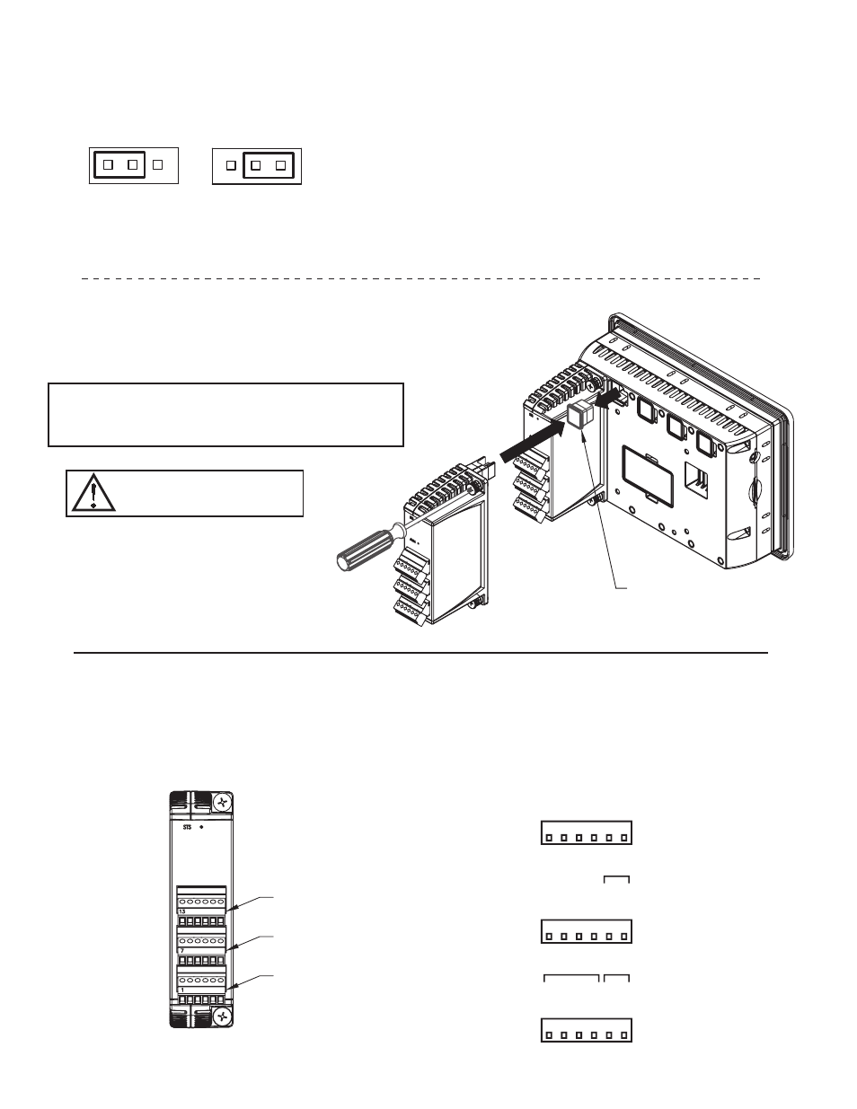
INPUT RANGE SELECTION
Select either ±20 mV or the ±33 mV
|
±200 mV range by placing the input jumper
in the appropriate location. The input jumpers are located on the side of the GMSG1
module.
± 20 mV
Range
± 33 mV
or
± 200 mV
Range
COM.
4
3
1 2
5
+SIG.
-SIG.
+EXC
COM.
6
-SIG.
OP3 COM.
13
OP1 COM.
ANALOG-
N/
C
OP3
+
ANALOG+
OP2
+
OP1
+
OP2 COM.
(OPT.)
2
1
8
7
9
+SIG.
10 11
+EXC
12
(OPT.)
2
15
14
N/
C
16 17 18
HARDWARE INSTALLATION
Modules must be installed beginning with slot 1 (left-most slot), with no
empty slots between the modules, and the order must match the modules order
in Crimson. Torque screws to 6.0 pound-force inch (96 ounce-force inch)
REMOVE RUBBER
MODULE PLUG
WARNING: Disconnect all power
to the unit before installing or
removing modules.
WIRING
WIRING CONNECTIONS
All conductors should meet voltage and current ratings for each terminal. Also, cabling should conform
to appropriate standards of good installation, local codes and regulations. When wiring the module, use the
numbers on the label to identify the position number with the proper function. Strip the wire, leaving
approximately 1/4" (6 mm) of bare wire exposed. Insert the wire into the terminal, and tighten.
Terminals 13 to 18
Terminals 7 to 12
Terminals 1 to 6
CAUTION: Some modules, depending on usage, may consume high
levels of power. This may limit the total number of modules that can
be installed on a single Graphite host. Check the Graphite module and
Graphite host data sheets for specific usage and power requirements.