Wiring, Wiring connections, Input connections – Red Lion GMUIN4 Universal Input Module User Manual
Page 4: Thermocouple voltage current
44
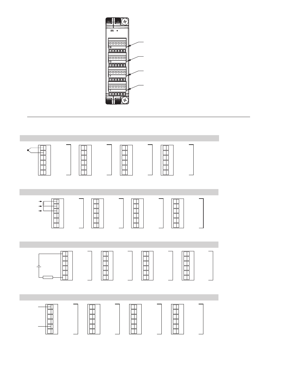
WIRING
WIRING CONNECTIONS
All conductors should meet voltage and current
ratings for each terminal. Also, cabling should
conform to appropriate standards of good installation,
local codes and regulationss and be suitably rated for
the temperatures of the environment to which it is
being installed. When wiring the module, use the
numbers on the label to identify the position number
with the proper function. Strip the wire, leaving
approximately 1/4" (6 mm) of bare wire exposed.
Insert the wire into the terminal, and tighten.
Terminals 13 to 18
Terminals 7 to 12
Terminals 1 to 6
Terminals 19 to 24
THERMOCOUPLE
VOLTAGE
CURRENT
INPUT CONNECTIONS
RTD
TC/RTD+
INPUT COM.
4-20 mA
0-10 V
N/C
RTD +EXE
1
3
2
5
4
6
SENSE
SENSE
EXC./
JUMPER
INPUT
1
TC/RTD+
INPUT COM.
4-20 mA
0-10 V
N/C
RTD +EXE
7
9
8
11
10
12
INPUT
2
TC/RTD+
INPUT COM.
4-20 mA
0-10 V
N/C
RTD +EXE
19
21
20
23
22
24
INPUT
4
TC/RTD+
INPUT COM.
4-20 mA
0-10 V
N/C
RTD +EXE
13
15
14
17
16
18
INPUT
3
6
5
4
3
2
1
0-10 V
4-20 mA
N/C
TC/RTD+
INPUT COM.
RTD +EXE
0-10 V
4-20 mA
N/C
TC/RTD+
INPUT COM.
RTD +EXE
+
12
11
10
9
8
7
INPUT
1
INPUT
2
18
17
16
15
14
13
0-10 V
4-20 mA
N/C
TC/RTD+
INPUT COM.
RTD +EXE
0-10 V
4-20 mA
N/C
TC/RTD+
INPUT COM.
RTD +EXE
24
23
22
21
20
19
INPUT3
INPUT
4
6
5
4
3
2
1
0-10 V
4-20 mA
N/C
TC/RTD+
INPUT COM.
RTD +EXE
12
11
10
9
8
7
0-10 V
4-20 mA
N/C
TC/RTD+
INPUT COM.
RTD +EXE
INPUT
1
INPUT
2
18
17
16
15
14
13
0-10 V
4-20 mA
N/C
TC/RTD+
INPUT COM.
RTD +EXE
24
23
22
21
20
19
0-10 V
4-20 mA
N/C
TC/RTD+
INPUT COM.
RTD +EXE
INPUT
3
INPUT
4
LOAD
POWER+
+
_
_
6
5
4
3
2
1
0-10 V
4-20 mA
N/C
TC/RTD+
INPUT COM.
RTD +EXE
12
11
10
9
8
7
0-10 V
4-20 mA
N/C
TC/RTD+
INPUT COM.
RTD +EXE
VDC-
VDC+
INPUT
1
INPUT
2
18
17
16
15
14
13
0-10 V
4-20 mA
N/C
TC/RTD+
INPUT COM.
RTD +EXE
24
23
22
21
20
19
0-10 V
4-20 mA
N/C
TC/RTD+
INPUT COM.
RTD +EXE
INPUT
3
INPUT
4