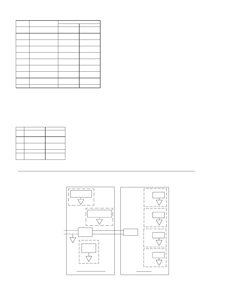
Block diagram for gmuin4 – Red Lion GMUIN4 Universal Input Module User Manual
Page 2
Cold Junction Compensation: Less than ±1 °C typical (±1.5 °C max) over -40
to 75 °C ambient temperature
Resolution: 0.1°
TYPE
MEASUREMENT
RANGE
WIRE COLOR
ANSI
BS 1843
T
-200 to +400°C
-328 to +752°F
(+) Blue
(-) Red
(+) White
(-) Blue
E
-200 to +730°C
-328 to +1346°F
(+) Violet
(-) Red
(+) Brown
(-) Blue
J
-200 to +760°C
-328 to +1400°F
(+) White
(-) Red
(+) Yellow
(-) Blue
K
-200 to +1350°C
-328 to +2462°F
(+) Yellow
(-) Red
(+) Brown
(-) Blue
R
0 to +1768°C
+32 to +3214°F
No Standard
(+) White
(-) Blue
S
0 to +1768°C
+32 to +3214°F
No Standard
(+) White
(-) Blue
B
+149 to +1820°C
+300 to +3308°F
No Standard
No Standard
N
-200 to +1300°C
-328 to +2372°F
(+) Orange
(-) Red
(+) Orange
(-) Blue
C
W5/W6
0 to +2315°C
+32 to +4199°F
No Standard
No Standard
mV
0 mV to 50 mV
N/A
N/A
TEMPERATURE INDICATION ACCURACY: ± (0.3% of span, +1 °C).
Includes NIST conformity, cold junction effect, A/D conversion errors,
temperature coefficient and linearization conformity at 23 °C after 20
minute warm up.
PROBE BREAK RESPONSE: Upscale drive, Input Fault Alarm bit set high,
ALx LED illuminates.
8. RTD INPUTS:
Type: 2 or 3 wire
Excitation: 150 µA
Lead Resistance: 15 Ω Max
Resolution: 0.1°
TYPE
INPUT TYPE
RANGE
385 100
Ω
platinum,
Alpha = .00385
-200 to +600°C
-328 to +1100°F
392 100
Ω
platinum,
Alpha = .003919
-200 to +600°C
-328 to +1100°F
672 120
Ω
nickel,
Alpha = .00672
-80 to +215°C
-112 to +419°F
Ohms Linear resistance 0
Ω
to 300
Ω
428
50
Ω
copper,
Alpha = .00428
-50 to +200 °C
-58 to +392 °F
Slope & Offset: Provides sensor error correction
TEMPERATURE INDICATION ACCURACY: ± (0.3% of span, +1 °C)
Includes NIST conformity, A/D conversion errors, temperature coefficient
and linearization conformity at 23 °C after 20 minute warm up.
PROBE BREAK RESPONSE: Upscale drive, Input Fault Alarm bit set
high, ALx LED illuminates.
9. CURRENT INPUTS:
Ranges: 0-20 mA or 4-20 mA
Programmable Scaling: ±30,000
Input Impedance: 10 Ω
Max. Continuous Overload: 100 mA
ACCURACY: ±0.1% of span
INPUT FAULT RESPONSE: Upscale Drive, Input Fault Alarm bit set high,
ALx LED illuminates below -2 mA, and above 22 mA for 0-20 mA range;
below +2 mA and above 22 mA for 4-20 mA signals.
10. VOLTAGE INPUTS:
Ranges: 0-10 VDC
Programmable Scaling: ±30,000
Input Impedance: 1 M Ω
Max. Continuous Overload: 50 VDC
ACCURACY: ±0.1% of span
INPUT FAULT RESPONSE: Upscale Drive, Input Fault Alarm bit set high,
ALx LED illuminates below -0.5 VDC and above +10.5 VDC.
11. CERTIFICATIONS AND COMPLIANCES:
CE Approved
EN 61326-1 to Industrial Locations
IEC/EN 61010-1
RoHS Compliant
UL Listed: File #E302106
12. ENVIRONMENTAL CONDITIONS:
Operating Temperature Range: -40 to +75 °C; limited to host
Storage Temperature Range: -40 to +85 °C
Operating and Storage Humidity: 85% max relative humidity, non-
condensing, from 0 to +50 °C
Altitude: Up to 2000 meters
13. CONSTRUCTION: Case body is aluminum and stainless steel. For indoor
use only. Installation Category II, Pollution Degree 2.
14. CONNECTIONS: Removable wire clamp screw terminal blocks
Wire Gage: 28-16 AWG terminal gage wire
Torque: 6.0 lbf-inch (96 oz-inch)
15. MOUNTING: Screws to host.
16. WEIGHT: 8 oz (224 g)
2
PORT 3
ETHERNET
B
ISOLATED
A
POWER
SUPPLY
+
-
VDC
GRAPHITE HOST
GMUIN4
PORT 2
A
COMMUNICATIONS
A
PORT 1
PROGRAMMING
G
ISOLATED
POWER
SUPPLY
INPUT 4
F
ISOLATED
INPUT 3
E
ISOLATED
INPUT 2
D
ISOLATED
INPUT 1
BLOCK DIAGRAM FOR GMUIN4