General specifications, Block diagram – Red Lion GMDIO Digital I/O Module User Manual
Page 2
2
GENERAL SPECIFICATIONS
1. POWER: Power will be supplied by the Graphite host device.
2. LEDs:
STS - Status LED shows module condition.
IN1-IN8 - LEDs are lit when associated input is active.
OP1-OP6 - LEDs are lit when associated output is active.
3. MEMORY: Non-volatile memory retains all programmable parameters.
4. INPUTS: DIP switch selectable for sink or source
Maximum voltage: +30 VDC, reverse polarity protected
Off Voltage: < 1.2 Volts
On Voltage: > 3.8 Volts
Input Impedance: Source Mode 10K ohms; Sink Mode 20K ohms
Input Frequency*:
Filter switch on: 50 Hz
Filter switch off: 300 Hz
* Actual useable frequency limited by communication to external device.
5. OUTPUTS: Outputs available as FORM-A relay or Solid State NFET.
Form A Relay Output:
Type: N.O.
The following pairs of relays share the common terminal: 1&2, 3&4, 5&6
Current Rating by pair: 3 Amps @ 30 VDC / 125 VAC resistive
1/10 HP @ 125 VAC
Life Expectancy: 200,000 cycles at maximum load rating. (Decreasing
load, increasing cycle time, and use of surge suppression such as RC
snubbers increases life expectancy.)
Solid State Output:
Type: Switched DC, N Channel open drain MOSFET
Contact Rating: 1 ADC max
VDS ON: < 0.2 V @ 1 A
VDS MAX: 30 VDC
Offstate Leakage Current: 0.5 µA max
6. ISOLATION LEVEL: 500 Vrms @ 50/60 Hz for 1 minute between the
following:
Inputs
Outputs
Graphite Host Power Supply Input
7. COMMUNICATIONS: Provided by the Graphite Host
8. ENVIRONMENTAL CONDITIONS:
Operating Temperature Range: -40 to +70 °C; limited to host
Storage Temperature Range: -40 to +85 °C
Shock to IEC 68-2-27: Operational 40 g (10 g, modules w/relays)
Operating and Storage Humidity: 85% max relative humidity, non-
condensing, from -40 to +75 °C
Altitude: Up to 2000 meters
9. CERTIFICATIONS AND COMPLIANCES:
CE Approved
EN 61326-1 to Industrial Locations
IEC/EN 61010-1
RoHS Compliant
UL Listed: File #E302106
10. CONSTRUCTION: Case body is all metal construction. For indoor use
only. Installation Category II, Pollution Degree 2.
11. CONNECTIONS: Removable wire clamp screw terminal blocks.
Wire Gage: 28-16 AWG terminal gage wire
Torque: 6.0 lbf-inch (96 oz-inch)
12. MOUNTING: Screws to host
13. WEIGHT: 8 oz (224 g)
PORT 1
PROGRAMMING
A
COMMUNICATIONS
PORT 2
POWER
SUPPLY
VDC
+
-
ISOLATED
PORT 3
ETHERNET
GRAPHITE HMI
INPUTS
ISOLATED
GMDIO14S
1
8
SUPPLY
POWER
OUTPUTS
1
ISOLATED
A
B
C
D
A
NFET
2
COM 1,2
COM 3,4
4
3
COM 5,6
6
5
F
OUTPUTS
RELAY
ISOLATED
5
COM 5,6
6
COM 3,4
3
4
COM
1,2
1
2
8
E
ISOLATED
1
INPUTS
GMDIO14R
POWER
SUPPLY
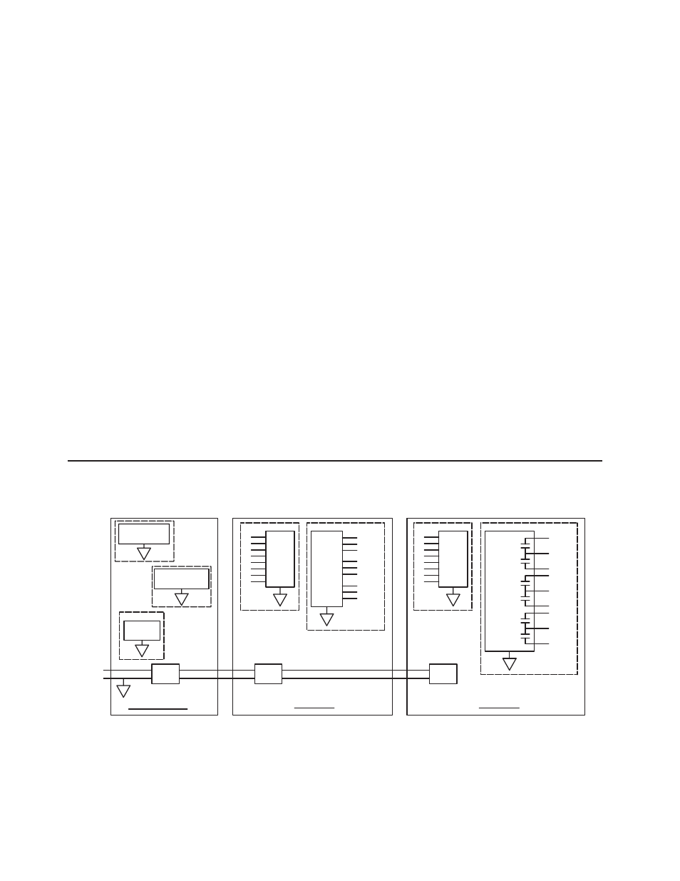
BLOCK DIAGRAM