Wiring, Caution – Vaisala DMT132 User Manual
Page 25
Chapter 3 _______________________________________________________________ Installation
VAISALA _______________________________________________________________________ 23
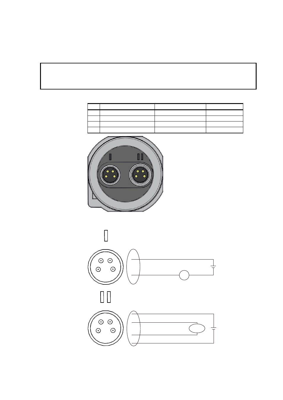
Wiring
CAUTION
The power supply lines on connector II are intended for use by the USB
service cable and the MI70 hand-held indicator. Do not connect other
power supplies to connector II.
Table 4
Connector Pinouts
Pin Connector I
Connector II
Wire color
1
VDC supply+
VDC supply+
Brown
2
Not connected
RS-485 D0-
White
3 GND
GND
Blue
4
Not connected
RS-485 D1+
Black
1101-082
Figure 14
Connectors I and II
+
−
1 = VDC+
3 = GND
mA
Vs
2
4
1
3
2
4
1
3
+
−
1 = VDC+
Vs
3 = GND
4 = RS-485 D1+
2 = RS-485 D0-
RS-485
1101-068, 1101-069
Figure 15
Connector Pinout
See also other documents in the category Vaisala Tools:
- DM500 (138 pages)
- DM70 (93 pages)
- DMT143 (76 pages)
- DMT152 (70 pages)
- DMT242 (4 pages)
- DMT340 (191 pages)
- DMT345 (185 pages)
- DPT145 (63 pages)
- DPT146 (71 pages)
- PTU300 (217 pages)
- PTB330TS (89 pages)
- PTB220 (10 pages)
- PTB220 (113 pages)
- PTB330 (144 pages)
- PTU200 (64 pages)
- PTU200MIK1 (18 pages)
- SPH10 (2 pages)
- SPH20 (2 pages)
- PTB110 (4 pages)
- PTB200 (30 pages)
- PTB210 (analog) (27 pages)
- PTB210 (serial) (32 pages)
- GM70 (68 pages)
- GMD20 (4 pages)
- GMK220 (18 pages)
- GML20 (2 pages)
- GML20T (2 pages)
- GMM20W (5 pages)
- GMM220 (6 pages)
- GMP231 (2 pages)
- GMP231 (90 pages)
- GMP343 (94 pages)
- GMR20 (2 pages)
- GMT220 (42 pages)
- GMW90 (101 pages)
- XMW90 (4 pages)
- MM70 (67 pages)
- MM70 (71 pages)
- MMT162 (66 pages)
- MMT310 (81 pages)
- MMT330 (181 pages)
- MMT330 (171 pages)