Transmitter structure – Vaisala DMT132 User Manual
Page 13
Chapter 2 __________________________________________________________ Product Overview
VAISALA _______________________________________________________________________ 11
Transmitter Structure
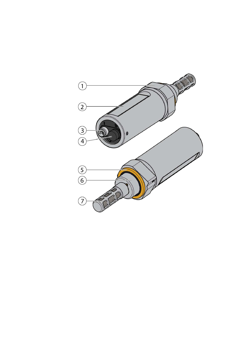
The structure of the DMT132 is shown in Figure 2 on page 11. The
transmitter body does not have user serviceable parts inside, and is not
designed to be opened. Opening the transmitter will void the warranty.
1101-083
Figure 2
DMT132 Transmitter Structure
where
1 = 30
mm
nut
2 = Transmitter
body
3
=
4-pin M8 connector I: analog output and operating power
4
=
4-pin M8 connector II (shown with protective cap):
Connection for service port (RS-485, service use only ) and
LED indicator plug
5
=
Sealing ring (included with every transmitter)
6
=
Connection thread (ISO G1/2")
7
=
Tube filter that protects the HUMICAP® and Pt1000 sensors
When the transmitter is delivered, the filter is protected by a yellow
transport protection cap that keeps the sensor dry. The transport
protection cap should be left on the transmitter during storage. Remove
the transport protection cap before installing the transmitter.