Connections, Cable wiring – Vaisala HMT310 User Manual
Page 32
USER'S GUIDE____________________________________________________________________
32 __________________________________________________________________ M210619EN-D
Connections
When HMT310 leaves the factory, its measurement ranges, output
scaling and quantities have already been set according to order completed
by the customer. The unit is calibrated at the factory and the device is
ready for use. The transmitter is delivered with a screw terminal
connector or with a detachable 5 m cable with eight wires for serial port,
analog outputs and 24VDC power supply. See the wiring instructions in
Figure 13 below and in Figure 14 on page 33.
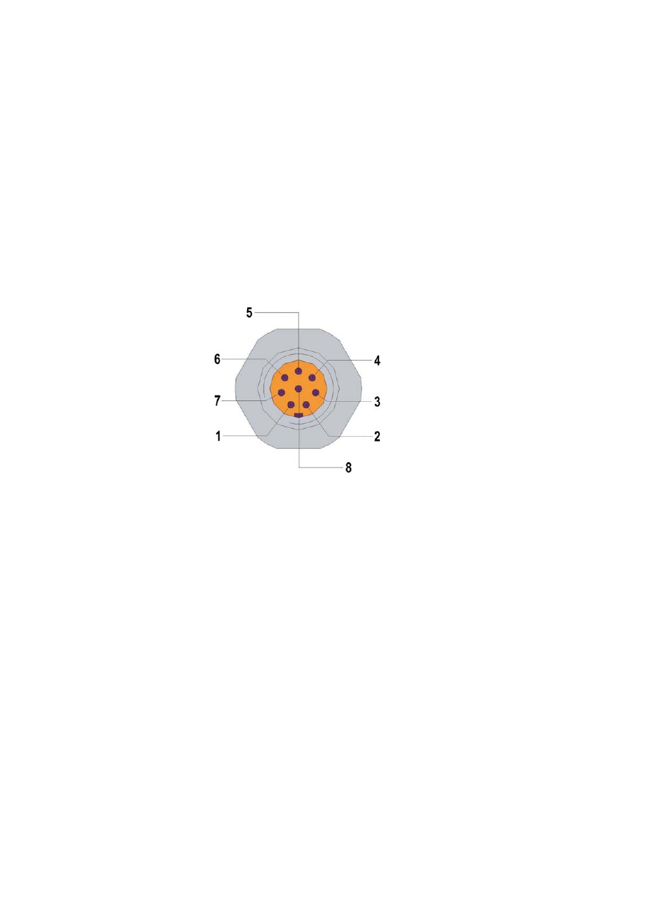
Cable Wiring
0507-044
Figure 13
8-Pole Connector
The following numbers and codes refer to Figure 13 above:
Color
Function
1 White (WHT)
= RS-232 TX
2 Brown (BRN)
= RS-232 GND
3 Green (GRN)
= CH2+
4 Yellow (YEL)
= CH1+
5 Grey (GREY)
= Supply-/CH1-/CH2 -
6 Pink (PINK)
= Supply+
7 Blue (BLU)
= RS-232 RX
8 Red (RED)
= Not connected