Figure 12, Power supply and voltage outputs (a), and serial, Communication and relay (b) – Vaisala HMT130 User Manual
Page 26
User's Guide _______________________________________________________________________
24 ___________________________________________________________________ M211280EN-B
1.
Remove the transmitter cover. See section Opening the Transmitter
2.
Insert the signal wires through the selected cable gland/conduit
fitting in the bottom of the transmitter or alternatively through the
rubber grommet at the back side of the transmitter.
3.
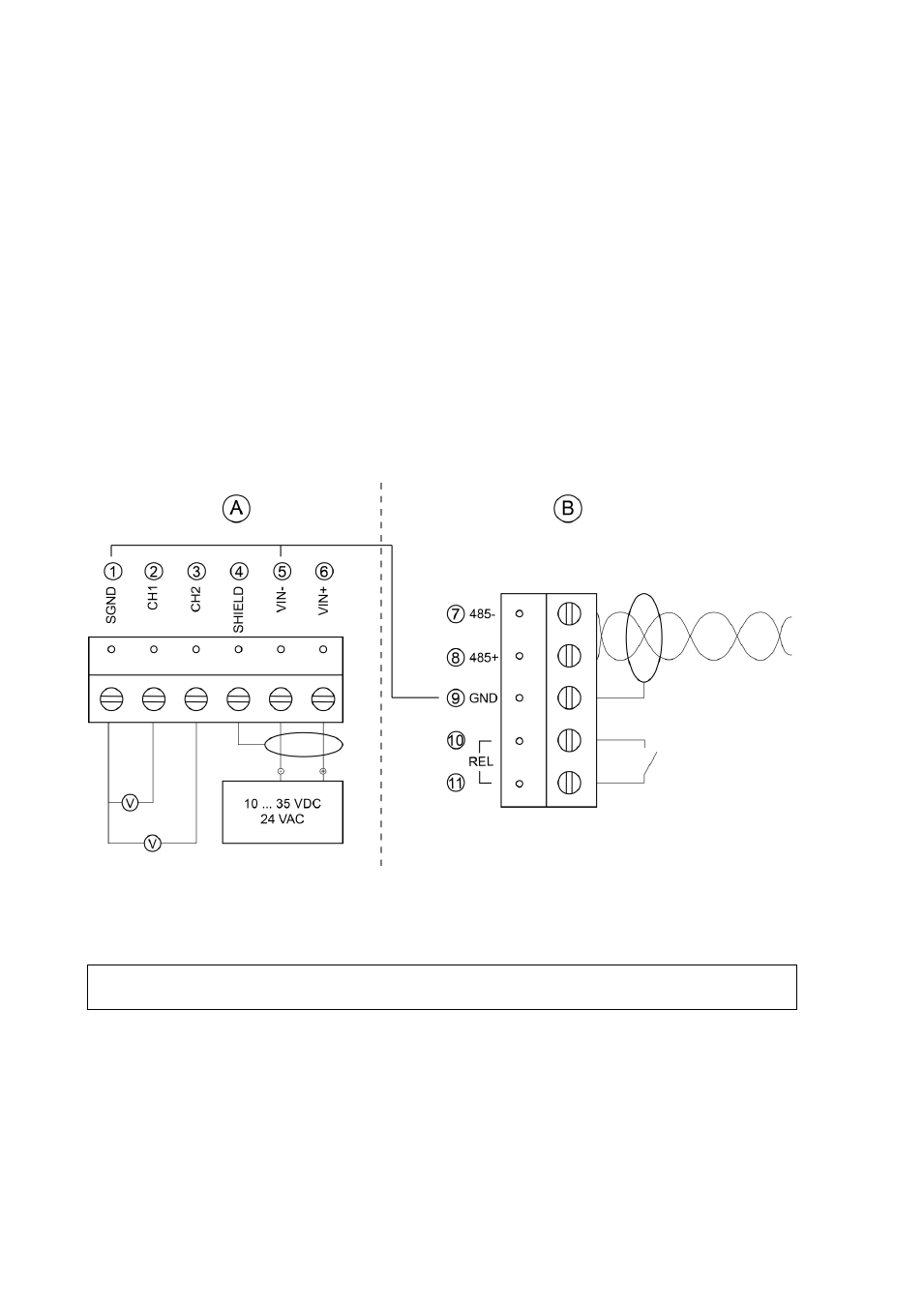
Connect the wires as indicated in Figure 12 below and in Table 3
on page 25. Suitable wire size is between 0.5 mm
2
and 1.5 mm
2
.
4.
Switch on the RS-485 bus termination switch if necessary. For
more information on the RS-485 bus termination switch see section
5.
Close the cover by keeping it slightly tilted and first attaching it to
the fixing snaps at the top of the enclosure base and then pushing
the lower part of the cover firmly forward until it locks. The
transmitter is ready for use.
1303-038
Figure 12
Power Supply and Voltage Outputs (A), and
Serial Communication and Relay (B)
NOTE
15 ... 35 VDC or 24 VAC is needed when using the 0 ... 10 V output.